

Concrete
Importance of TSR


Procyon Mukherjee discusses the importance of the thermal substitution rate in the use of alternative fuels in the first part of this two-part series.
It was 22nd October 2019, and we were in Wuhan, visiting the world’s largest kiln that was being installed with the design-TSR of 60 per cent, which meant from the inception the system would be ready to take in higher quantity of RDF, largely from the municipal wastes generated at Wuhan. The overall schema included several co-processing units near Wuhan and then the eventual logistics of moving them through barges on the Yangtse river and then through pipelines into the different sections of the kiln and the pre-heater. We were quite astonished to see that it was the municipality of Wuhan who came forward with the entire scheme including logistics that helped the setting up of the plant – essentially a means for incineration of the entire municipal waste of Wuhan.
The rest of the world may not have such a denouement, rather a step-by-step approach of increasing the TSR, with more and more usage of alternate fuels. Thus, in most cases it is an incremental approach, the investments included. It is worthwhile to look at the journey of alternate fuel usage in cement kilns across the world over the last three decades and what are some of the critical investment pathways for increasing TSR.
The first major use of alternative fuels in the cement manufacturing industry emerged during the mid-1980s. The primary goal in substituting fossil fuels was to enable the industry to remain economically competitive, as fuel consumption accounts for almost one-third of the cost of producing clinker. Any positive impact on the environment was considered an added benefit. Since then, there has been increasing sensitivity to the environmental impact of human and industrial activities. Beyond the cost-cutting benefits of alternative fuels, use of these fuels can contribute greatly to the environmentally sound disposal of waste and to the mitigation of greenhouse-gas emissions (GHG).
Therefore, key cement players started to consider alternative fuels as a lever to improve their contribution to sustainable development and as a key component of corporate social responsibility.
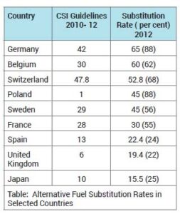
The data in the bracket is the current number for TSR. The obvious case in point is the stratospheric increase in TSR rates in Poland. This needs some discussion. The case study on Poland throws some pointers as to how the journey from zero to 88 per cent has been achieved. The notable steps have been:
1. The willingness of Polish cement companies to reduce their operating costs by quickly replicating the alternative fuel experience of international cement groups
2. The enforcement of Polish waste regulations in order to conform to relevant European
Union directives, namely the Waste Framework Directive, the Waste Incineration Directive and the Landfill Directive.
The second one is one of the fundamental reasons to drive the use of alternate fuel. The journey had its humble beginnings with a small state tax imposed on land fill waste (which was collected from the same people who produced the waste) and then the increase of this tax over time, with the transfer of responsibility of waste collection to the land fill operators. Parallelly the ‘extended producer responsibility’ sparked off the implementation of the first waste shredding line to produce refuse-derived fuel (RDF).
In 2005, Germany adopted a ban on the landfilling of recyclable and organic waste, leading to overproduction of RDF. Poland’s shift toward alternative fuel development based on RDF was thus supported by importation of the fuel from Germany for five years, before Germany increased its own waste burning capacity. At that point, the alternative fuel substitution rate in Poland reached 20 percent. In 2008, the state tax was increased sharply, climbing from €4 per tonne in 2007 to about €17 per tonne, with a further doubling announced within the next 10 years. The enforcement of this tax for municipal waste incited waste management companies to invest in alternative solutions.
At that point, shredding line operators were sourcing waste from the industrial sector (obtaining good-quality waste for a low gate fee) as well as from the municipal waste sector, with large cities being the main providers. The extension of sourcing to include municipal waste resulted in a degree of downgrading of RDF quality, but the cement sector continued the effort and pushed the substitution rate to 40 per cent in 2010.
Once the capacity of RDF production lines reached an equilibrium with the alternative fuel capacity of cement plants, the cement companies were able to pressure RDF producers to further improve the fuel quality. To face this new demand, RDF producers had to innovate, improving the quality of the RDF significantly through better sorting and drying sequences (thermal or biological). In parallel, the cement plants developed new tools to improve drying, such as by installing thermal dryers that used the waste heat from the kilns. A new increase to the state tax then put more waste on the market—and at a better price—confirming the trend toward alternative fuel use.
But the crucial area of investment remained how to arrest the pitfalls of high RDF usage in the kilns as there were issues around chlorine, kiln operational stability, enabling the efficient use of diverse and often challenging fuel types, integration of the system with usage of multiple fuels including diverse alternate fuels and monitoring and control. It is in this regard that several specific investments had to be targeted. The lead in this was taken by Germany and followed by all others to see how increase in thermal substitution rates did not come in the way of either impacting the efficiencies or the environment and efforts were directed to create not only a balance but a way to get to 100 per cent of alternate fuel usage, virtually paving the way for 100 per cent TSR.
Some of the most commonly used alternative fuels in the cement industry are biomass, industrial and domestic waste materials, scrap tires, and sewage sludge. The high temperatures, long residence times, and alkaline environment in the cement kiln can prevent the formation of hazardous volatile compounds, making it a suitable option for co-processing waste materials as alternative fuels during cement production. Although the substitution of fossil fuels such as coal and pet coke with alternative fuels can potentially reduce total CO2 emissions from the cement industry, the reduction potentials are often marginal (in the range of 1- 5 per cent for most cases and up to 18 per cent of current CO2 emissions in a few cases) and depend on the source of biogenic emissions. Moreover, due to higher concentrations of sulphur, nitrogen, chlorine, heavy metals, or other volatile matter in some alternative fuels, co-processing can increase emissions of non-CO2 air pollutants of concern in some cases. Thus, an eye on not increasing the emissions (not just CO2 but also SOX and NOX) became a priority. This required investments over time as the RDF usage increased.
Let us see some of these investments in details, like Chlorine By-Pass, Rotating Hot Disc, ID Fan Modification, ESP Fan Modification, etc would be needed the moment the TSR rates would be approaching plus 30 per cent:
1. Chlorine by-pass: This investment is directed at mitigating and protecting a number of
things like:
Managing chlorine build-up
– Alternative fuels like waste-derived fuels often contain high levels of chlorine. This can lead to an accumulation of alkali chlorides in the kiln system.
– Chlorine build-up can cause operational problems, such as the formation of buildups or rings in the kiln and preheater systems, disrupting the material flow and reducing efficiency.
Improving kiln operation stability: High chlorine content can lead to corrosion and fouling of equipment. By removing excess chlorine, the system operates more stably and with fewer maintenance interruptions.
Protecting product quality: Excess chlorine can impact the clinker quality, leading to undesirable properties in the cement. The bypass system helps maintain consistent and high-quality clinker production.
Facilitating use of diverse fuels: Many alternative fuels, such as municipal solid waste, industrial waste, or tires, are economical but contain high chlorine levels. The bypass system enables cement plants to use these fuels without compromising efficiency
or quality.
Reducing environmental impact: Chlorine in the kiln system can lead to the formation of dioxins and furans, which are harmful pollutants. By extracting chlorine from the system, the bypass reduces the risk of these emissions.
How the system works:
The chlorine bypass system extracts a portion of the kiln gas from a specific point (often the kiln inlet) where the alkali chlorides are in a gaseous form. These gases are cooled rapidly to condense and separate the chlorides, which are then collected and disposed of appropriately.
There are eight components of the system:
Gas extraction system
- Function: Extracts a portion of kiln gases from a strategic location, typically near the kiln inlet where volatile alkali chlorides are in gaseous form.
Key components:
– Gas ducts with high-temperature resistance.
– Dampers to control the volume of extracted gas.
Rapid cooling system
- Function: Quickly cools the extracted hot gases to condense alkali chlorides and other volatiles, preventing them from recirculating into the kiln system.
- Key components:
– Water sprays or air quenching systems for
rapid cooling.
– Heat exchangers, if heat recovery is integrated.
Cyclones or bag filters
- Function: Separates condensed alkali chlorides and dust from the cooled gas stream.
- Key components:
– High-efficiency cyclones for coarse particle separation.
– Bag filters or electrostatic precipitators for fine particle removal.
Disposal system for collected byproducts
- Function: Safely manages and disposes of extracted chlorides and dust.
Key components:
– Conveyors or pneumatic transport systems.
– Silos or containment units for storage before disposal.
Bypass gas cooling and conditioning system
- Function: Further conditions the bypass gas before reintegration into the system or venting.
- Key components:
– Cooling towers or gas conditioning towers.
– Water injection systems for temperature control.
Control and automation system
- Function: Monitors and optimises the bypass system to ensure it operates efficiently and safely.
- Key components:
– Sensors for temperature, pressure, and chlorine content.
– Programmable logic controllers (PLCs) for real-time adjustments.
Heat recovery system (optional)
- Function: Captures waste heat from the bypass gases for use in other processes, improving energy efficiency.
- Key components:
– Heat exchangers.
– Steam generators or preheaters.
Integration with main kiln system
- Function: Ensures that the bypass system operates in harmony with the kiln process without disrupting clinker production or fuel efficiency.
- Key components:
– Ducts and valves for gas reintegration or venting.
– Interfaces with kiln control systems.
2. Combustion chamber hot disc
The installation of a combustion chamber (hot disc) in cement kilns for alternate fuel installations serves several critical purposes, enabling the efficient use of diverse and often challenging fuel types. Here’s a breakdown of its key roles:
Efficient combustion of alternative fuels
- The hot disc provides a dedicated zone for the complete combustion of alternate fuels, including those with varying calorific values, moisture content, and particle sizes.
- This ensures that even low-grade or coarse fuels (e.g., tires, municipal solid waste, biomass, or industrial waste) can be burned effectively.
Improved heat transfer
- The combustion chamber is designed to optimise heat generation and transfer, supplying the kiln with the necessary thermal energy.
- It reduces reliance on primary fossil fuels like coal or petcoke, lowering operating costs.
Reduced emissions
- Proper combustion in the hot disc minimises the release of harmful emissions, such as carbon monoxide (CO), volatile organic compounds (VOCs), and unburned hydrocarbons.
- This helps the cement plant meet environmental regulations and sustainability goal
- Enhanced kiln operation stability
- Burning alternative fuels in the combustion chamber isolates their impact from the main kiln, ensuring stable temperatures and operation within the kiln.
- It minimises disruptions caused by the inconsistent burning behaviour of alternative fuels.
Handling difficult fuels
- The hot disc is specifically designed to process fuels that are challenging to handle in the main kiln or calciner, such as large solid fuels (e.g., tires or large biomass pieces).
- The chamber’s design accommodates prolonged fuel residence time and high temperatures, ensuring complete combustion.
Optimised energy efficiency
- By burning alternate fuels close to the kiln inlet or calciner, the hot disc provides pre-heated gases to the kiln system, improving energy efficiency.
- It contributes to a more uniform temperature profile, enhancing clinker quality.
Increased use of waste-derived fuels
- Many cement plants aim to increase their Thermal Substitution Rate (TSR)—the percentage of energy derived from alternative fuels. The hot disc facilitates this transition by enabling higher volumes and more diverse types of alternate fuels to be used safely and efficiently.
Overall benefits
The hot disc system allows cement plants to:
- Reduce dependency on fossil fuels
- Lower operational costs
- Improve sustainability by using waste as a resource
- Comply with stricter environmental regulations.
Rotating hot disc
- Function: The central component where alternative fuels, such as coarse solids (e.g., tires, plastics, or biomass), are introduced and combusted.
Key features:
- Rotating design for even fuel distribution.
– High-temperature resistance to handle intense combustion conditions.
– Adjustable speed to optimise fuel combustion time and efficiency.
Fuel feed system
- Function: Delivers alternative fuels to the hot disc in a controlled manner.
- Key components:
– Conveyors, pneumatic systems, or screw feeders for fuel transport.
– Chutes or injection systems for precise fuel placement.
– Hoppers or silos for storage of alternate fuels before feeding.







Concrete
Nuvoco Marks 10 Years, Targets 35 MMTPA Capacity by FY28
Nuvoco celebrates a decade of growth, targeting 35 MMTPA cement capacity by FY28.

Concrete
J&K Government Notifies City Gas Distribution Policy
Policy targets PNG and CNG expansion across all 20 districts
Concrete
JSW Cement Commissions 1 MTPA Grinding Unit at Nagaur
Nagaur unit lifts JSW Cement’s grinding capacity to 25.10 MTPA

Nuvoco Marks 10 Years, Targets 35 MMTPA Capacity by FY28

J&K Government Notifies City Gas Distribution Policy

JSW Cement Commissions 1 MTPA Grinding Unit at Nagaur

JSW Cement Commissions 1 MTPA Unit in Rajasthan

Wonder Cement appoints Mahesh Singh as VP Corporate Brand Communication
Nuvoco Marks 10 Years, Targets 35 MMTPA Capacity by FY28
J&K Government Notifies City Gas Distribution Policy
JSW Cement Commissions 1 MTPA Grinding Unit at Nagaur
JSW Cement Commissions 1 MTPA Unit in Rajasthan
Wonder Cement appoints Mahesh Singh as VP Corporate Brand Communication
-
 Concrete4 weeks ago
Telangana to Supply Subsidised Cement for Indiramma Houses
-
 Concrete2 weeks ago
Andhra Pradesh Clears Rs. 30 bn My Home Cement Plant
-
 Concrete2 weeks ago
JSW Cement Receives Rs. 2.3 bn GST Demand Notice
-
 Concrete4 weeks ago
Centre Defers Clearance for Limestone Mine Near Bustard Habitat