Connect with us

Concrete

Pyroprocessing and Kiln Operation

Published

on

Shares

Dr SB Hegde, Visiting Professor, Pennsylvania State University, United States of America, talks about pyroprocessing and the role of preheater, rotary kiln and clinker cooler in the cement manufacturing process. In this two-part series, we will learn all the various factors that aid pyroprocessing.

The composition of Ordinary Portland Cement (OPC) has remained largely the same since the last century and similarly the production process and the chemistry is almost the same. What changed is considerable technological upgradation in the equipment and software for cement manufacture. As a result, more than 12000 tonne per day clinker production from a single kiln has become a reality with latest state of the art fuzzy logic, on line monitoring, advanced operating system with latest data analytics etc. The manipulation and human intervention are relatively reduced, which has resulted in consistent operation, consistent quality parameters both in semi-finished and finished products.

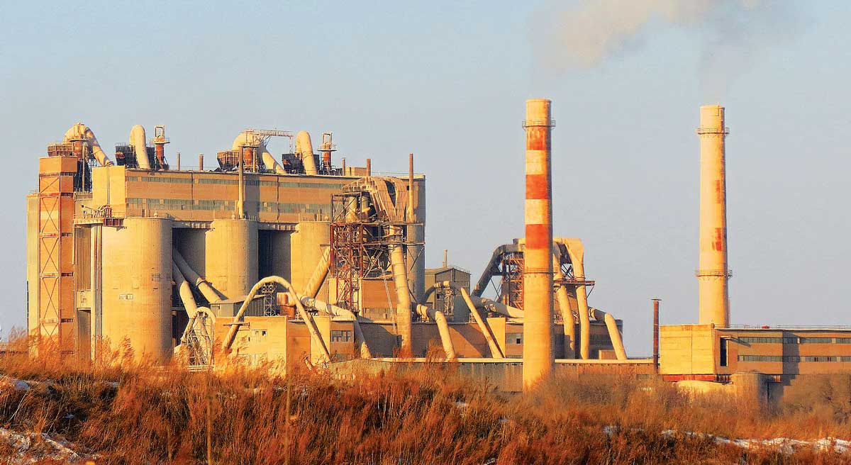
Pyroprocessing in a cement plant comprises a preheater, rotary kiln and clinker cooler. Pyroprocessing section is the heart of a cement plant as actual cement clinker production takes place in kilns. The size of a cement plant is determined based on the pyroprocessing section and the sizes of all other equipment are determined to match pyroprocessing. Cyclones are basic units in a preheater system. Pressure drop and change of temperature of gas across each stage determines the efficiency of cyclones. Introduction of Low Pressure drop (LP) cyclones has brought the pressure drop across each stage to around 50 mm WG from around 150 mm WG in conventional cyclones. This has resulted in more and more plants adopting 5 or 6 stages of preheater. A typical 6 stage preheater with LP cyclones will have a preheater exhaust gas temperature of around 250°C and draught of around 500 mm WG. This in turn led to decrease in preheater fan power consumption.

The reduced temperatures at preheater exhaust contribute to environmental improvement. Cyclone separators are used in preheaters on cement plants to separate the raw material for gases. A very tall preheater means more power is required to operate the plant.

It is always desired for a minimum preheater height to operate the plant economically. Due to the preheater arrangement and layout design cyclones decide the height of the preheater. Pressure drop-in cyclones play an important role in determining the cost of operation of cyclone separators. High pressure drop means more power required to operate the cyclone.

Main KPIs of Clinkerisation

Production rate, ton per dayRun time factor in percentage Specific Heat Consumption in kcal/kg-clinkerSpecific Power Consumption in kwh/ton-clinkerSpecific Cooling Air in kg-air/kg-clinkerSpecific brick Consumption in grams/ton-clinker

The overall process of conversion from raw meal to clinker being endothermic demands a theoretical heat of about 380-420 kcal/kg-clinker. However, the rest of the specific heat consumption as tabulated above constitutes heat losses from preheater exhaust gases, clinker, cooler exhaust gases, preheater dust and radiation losses. Heat loss distribution across different elements can be established through heat balance and process audit of the pyro section. Fuels used commonly to provide heat for the conversion processes are coal, pet coke, and alternate fuels. Alternative fuels like pet rubber tyres, municipal wastes, clinical wastes, greases, rice husks, ground nut husks etc. These materials are being used to become cost effective and to fulfil the condition of Pollution Control Boards while granting the consent to establish and consent to operate the cement plants.

Kiln Operation Guidelines

Based on my experience in cement plant operation, I have jotted down in this paper the important parameters to be maintained for achieving better kiln reliability factor, optimal cost and better quality of clinker production. Cement kiln operation is an ‘art’ once mastered.

Kiln Speed should be such that volumetric loading is within the range 10-15 per cent and heat transfer is maximised.  Precalciner kilns generally rotate at 3.5-6 rpm. Under normal conditions, the kiln should be run with as high rpm as possible. Higher kiln rpm improves clinker mineralogy and grindability. Speed control is used to take care of usual kiln disturbances like coating fall down with the other controlling parameters like, fuel rate, preheater fan rpm and kiln feed rate.

Fuel Rate is frequently used as a controlling parameter in kiln operation. Fuel is regulated in the kiln and pre-calciner to maintain required temperature. Oxygen (O2) and carbon monoxide (CO) must be considered first before increasing fuel rate.

Feed Rate is generally maintained in a stable kiln operation. When the control actions, like kiln speed, fuel rate and air control fail or are expected to be insufficient to control kiln disturbance, feed rate is changed as required.

Preheater Fan Speed is varied to fulfil air requirement in kiln system and maintain oxidising conditions in kiln. ID fan speed is not changed frequently in normal kiln operation, unless feed or fuel changed significantly.

Kiln Inlet Analyser gas composition reveals the process (kiln) stability and combustion efficiency. With a good flame in kiln O2 at kiln inlet will be about 1-2 per cent and CO less than 200 ppm, while as it has been observed that an unstable flame may yield in excess of 500 ppm CO with even 3 per cent O2.

Nitrogen oxides (NOx) measurements at kiln inlet gives an early indication of changing burning zone temperatures conditions, before it is reflected in kiln torque trend. It is important to mention that the kiln inlet gas analyser probe position should be inside the kiln to avoid leakage air through the inlet seal to be sucked with sample gas. PC-Gas Analyser is generally installed in the outlet duct from the bottom cyclone to avoid frequent jamming of gas filter due to high dust load in PC outlet duct. Oxygen level should be between 0.5-1.5 at CO less than 100 ppm.

Preheater Outlet Analyser: In preheater down-comer analyser serves both purposes, to measure leakage across the tower and the overall combustion conditions in kiln system. Moreover, it serves as a safety equipment for all critical equipment in upstream gas circuits like ESP, Bag house etc. Oxygen content of 1.5 to 2.5 per cent is considered good at a preheater outlet. Prompt action is recommended if CO increases more than 0.5 per cent.

Lower Cyclone Temperature is considered most important and stable temperature in preheater to control pre-calciner fuel rate. It is generally maintained manually or by PID loop in the range of ±10oC, in the range 850-900oC to ensure calcination between 90 per cent to 95 per cent.

Burning Zone Temperature is monitored by radiation pyrometer. Maintaining constant burning zone temperature means, clinker of constant quality and grindability from a consistent kiln feed. Radiation pyrometer gives a relative value of temperature on the basis of visibility (colour) in the burning zone and can be used as a decisive parameter in stable kiln operation.

Secondary Air Temperature should be as high as possible. It reflects the stability of clinker bed in cooler and the heat recuperation from hot clinker. The higher the best, in the range of 800-1050oC.

Cyclone Cone Drafts: In operation of the kiln, it is a lifeline to monitor all preheater drafts, particularly cyclone cone drafts. Cone drafts in preheater cyclones give an important indication of cyclone jamming along with the other parameters like temperature.

Kiln Back End Temperature indicates the overall stability of kiln operation. It is generally maintained very closely. Variation in kiln back-end temperature indicates either change in burning zone or a change in calciner, hence is of pivotal importance to infer both areas of interest. Back-end temperature is normally maintained at 105oC. Flame shape will determine the flame length and therefore, burning zone length. Flame should be as short as possible, but care should be taken to avoid thermal abuse of refractory due to shorter and one-sided flames.

Kiln Hood Draft should be slightly negative and must be maintained closely between 0 to -2 mm H2O preferably by PID control loop with Cooler vent fan speed. More negative will increase cold air leakages into the kiln through outlet seal and hood, while positive pressures are unsafe.

Cooler Bed Height and Undergrate Pressures: Maintaining constant clinker bed height is a key to stable cooler operation. Undergrate pressure reflects bed resistance and changes with clinker size. To maintain constant Undergrate pressure cooker speed is varied manually or in auto-mode by PID control loop. Constant bed height ensures stable secondary and tertiary air temperatures.

Cooling Air Quantity is maintained to ensure cooling of clinker and heat recuperation from hot clinker from kiln. Specific air usage is generally considered as a key performance indicator of a cooler. New generation coolers can cool the clinker to temperatures as low as 65oC over ambient with a specific air consumption of 1.7 kg/kg-clinker. Generally cooling fans are designed at 2.7 kg-air/kg clinker.

Kiln Torque Load It is a very good indication of the burning zone state, accurate at 70 to 80 per cent of the time. It does not give any major indication for planetary cooler kiln as the load is not always uniform.

Some Important Components of Modern
Kiln System
Main components of kiln system are:
Preheater: Preheaters as name implies serves the purpose of heating raw meal to a temperature where calcination or dissociation of CO2 begins in calciner. Preheater consists of 4-6 low pressure cyclones one over the other. Number of cyclones depends on the natural humidity (moisture) in raw materials, in other words the drying capacity required to dry out raw materials in a raw mill. Five or six stage preheaters are commonly existing in cement plants.

In order to increase heat utilisation in the kiln system, six stage cyclones are as well installed in many cement plants. However, increasing cyclone stages beyond six does not look economic any more, as the quantum of heat saving is not significant to justify it, moreover the increased pressure drop across preheater outbalances the improvements due to additional cyclones.

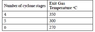
Preheater Exit Gas Temperature (EGT): Preheater exit gas temperature depending on multiple many factors, however the range for 4, 5 and 6 stage cyclone preheater is tabulated below for reference:

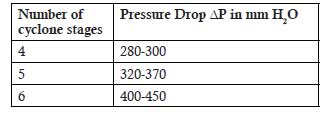
Pressure drops in Preheater ΔP: With the evolution of low-pressure cyclones, it became feasible to go from 4-stage cyclone preheater to 6-stage preheater and harvest more heat in the kiln section. For reference are tabulated the pressure drop values across the 4, 5 and 6-stage preheater.

Brick Lining of Cyclones: All preheater components need to be lined from inside with appropriate refractory to save shell/components from heat and to hold heat inside for process use. Refractory castable, bricks and insulation bricks are used in preheaters.

Calciner. Calciner is meant for decomposition of carbonates into reactive oxide calcium oxide. Calcination is an endothermic process and needs heat energy of about 420 kcal. Raw meal is taken in the calciner from the last but one stage of the preheater. Heat for calcination is supplied through secondary firing in the calciner and combustion air is taken from the cooler through tertiary air duct. Various configurations of calciner are existing in modern kiln systems.

Development of calciner have been very significant in multiple in cement industry like:
Burning is more uniform and hence clinker produced is also uniform in quality.Raw meal need not be ground as fine as required for kilns carrying calcination duty.Fuels poorer in quality can be burnt.Raw materials high in alkalies and chlorides could also be used.Throughput capacity of kiln increases 5 times.

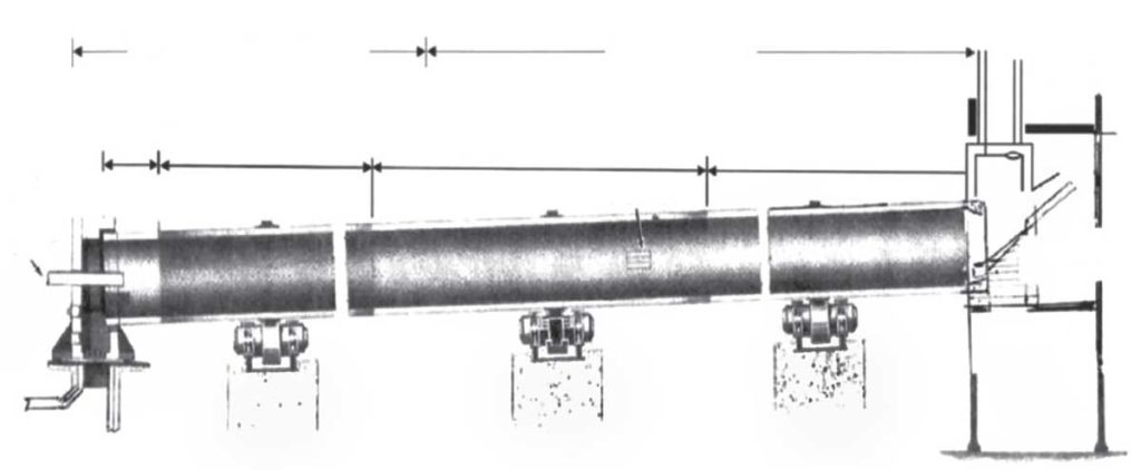
Rotary Kilns: Rotary kiln is a rotating cylinder, installed at an inclination of 3.5 to 4 per cent to facilitate material movement. Length and diameter of kiln is decided for the required capacity throughput. Main factors dictating size of kiln are the retention time (25-30 minutes) of material in kiln, degree of filling (10 to 17 per cent) and thermal loading of burning zone (2.8-4.8 x 10⁶ kcal/h/m2).

Precalciner kilns are shortest in length, as 90 to 95 per cent calcination is completed outside the kiln. L/D of three tyre kilns is between 14-17 and for new kilns like ‘Rotax kiln’ it is only 12-13. Kilns are commonly supported on three supporting stations. Each supporting station has 2 rollers and 4 bearings. All rollers are mounted on one fabricated bed plate. Tyre rests on rollers which have an angle of about 30 degrees at the centre of the kiln. Kiln is lined with refractories bricks of 150-250 mm thickness, depending on the diameter of kiln. Basic bricks are preferred in the burning zone; however, 75 per cent alumina bricks are still used for cost consideration. Rest of the kiln is lined with ~ 45 per cent alumina bricks.

Kiln Components
Inlet and outlet seals to prevent cold air ingression in the kiln system.Hydraulic thruster arrangement to prevent slipping of kiln downhill, and to ensure proper floating of kiln.Kiln Drive to rotate the kiln at required speed.Auxiliary Drive for start-stop, maintenance and emergency cooling in case main drive stops/trips.Kiln Burner to insert coal, oil or gas into kiln from the kiln hood. Multichannel burner is used to have a control on flame geometry and use minimum primary air.Nose ring fans to cool kiln outlet tip casting plates nose of kiln.Shell cooling fans are used to cool the shell, to promote coating formation in kiln burning zone areas.

Cooler
Clinker cooler serves two main objectives of cooling clinker from temperature of about 1350oC to the temperature (65-150 0C), where it can be handled by conveyors like pan conveyors, chain, elevators etc. and heat recovery from hot clinker coming out of the kiln. A huge development has happened in clinker coolers designs and types as well. Grate cooler with a take-off for precalciner is generally required for precalciner kilns. Cross bar coolers are used in new plants to achieve cooling efficiencies (>70 per cent) and less maintenance burden. New coolers are designed for the capacity to be handled with the loading of 40-55 tpd of clinker cooled/m2 of grate area. Cooling air requirement is generally designed at 2.2-2.5 nm3/kg-clinker. Either hammer crusher or roller crusher is used to break lumps of clinker before coming out from the cooler. Water spray or air to air heat exchanger is used to cool down cooler vent air before dedusting in ESP or bag filter.

  • How to Check or Control Heat Consumption?
    Based on my experience the following points should be observed, checked and optimised on day-to-day basis:
    Prepare a consistent raw mix: Raw mix characteristics (fineness, quartz content, etc…) and its consistency have an impact on heat consumption. Clinker quality (C3S target) has to be optimised too.
  • Control oxygen levels in kiln and preheater: While an oxidising atmosphere in the kiln is necessary for a good combustion, the oxygen level has to be minimised. Limiting false air in the kiln line is also beneficial to minimising heat consumption. Reliable gas analysis systems are paramount to master it.
  • Optimise fuel combustion: Burners have to be adapted to the type of fuel used by the plant and must be operated within specific parameters (specific impulse and swirl).An oxidising atmosphere is obtained by an adequate draught and a good preparation of the fuel (fineness for solid fuels or atomisation for liquid fuels.
  • Master kiln stability: Consistency of kiln feed and fuel dosing is necessary to master combustion. This can be confirmed by clinker free lime results and consistency. A process control system when used appropriately helps minimise heat consumption.
  • Optimise cooler efficiency: Optimised airflow distribution, good clinker distribution and size as well as maximised clinker bed depth in the cooler have a beneficial impact on heat consumption; in addition, control loops monitored by a control system optimise operation.
  • Master pre-heater and calciner operation: Minimising gas by-pass (flap valves), optimising meal distribution (splash boxes), good material / gas distribution (cyclones efficiency) and managing build-ups are key factors to master pre-heater operation, as well as calciner operation (when there is one).
  • Optimise kiln throughput: Operating a kiln at maximum stable throughput minimises heat consumption; identifying current bottlenecks is critical to understand margin for control.
  • Maximise kiln reliability factor: Heat consumption is positively impacted by clinker line reliability; reporting all kiln incidents and analysing them during regular team meetings are critical to improve reliability.
  • Minimise wasted cement kiln dust or kiln dust loss: Wasted cement kiln dust and kiln dust losses should be monitored and minimised within the clinker quality and kiln process constraints.
  • Apply operating procedures with skilled CCR: Operators procedures to start up and shut down the kiln, to manage small kiln stops or to control kiln instabilities have to be written and applied. Kiln operators’ qualification can be improved through skills and knowledge improvement programmes.

Positioning of the Burner

The optimum position depends on many factors. In earlier days, it was a common practice to point the burner a little bit down compared to the kiln axis, in the direction of the charge. This was primarily done to compensate for the tendency of the flame to go upward due to convection and entrainment by the secondary air.

Today, with modern high momentum burners, this is no longer recommended. The jet momentum being stronger, if you point the burner toward the charge, the risk is that the flame will touch the charge. The local reducing conditions would increase Sulphur circulation and increase the risk of coating and blockages in the preheater. Consensus is that high momentum burners should be placed parallel to the kiln axis.

Basic positions would be on the kiln axis, but the burner can also be shifted sideways (still parallel to the kiln axis). Some recommend shifting the burner horizontally away from the charge when using coarse waste fuel to limit the risk that coarse particles would fall into the charge. Similarly, if you use only fine, easy to burn fuel, the burner can be shifted toward the charge to improve heat exchange. As radiation is the primary heat exchange mechanism, the effect is however limited.

Concerning insertion depth, in theory, the further inside is the better. This is to get away from the perturbation of the change of direction of the secondary air and to improve the precooling zone to avoid snowmen in the cooler. There is however a limit due to the length and related weight of the burner and the risk of damage by big pieces of coating falling on the burner. Usual insertion depth would be 50cm-1m inside the kiln. But many kilns operate with the burner just at the limit of the kiln (0cm). Having the burner outside the kiln is generally not recommended.

The burner is usually set at a small angle to the kiln axis and slightly directed on to material. It must be remembered that the material is being cooled by the stream of secondary air flowing over it provided no overheating effects take place in the material; it is thermodynamically desirable to let the flame sweep over it. To prevent the material is getting too hot in to the cooler the final area of the kiln outlet is used as cooling zone, the point of burner is therefore normally pushed forward into the kiln for a distance (0.5 – 1.25 m) in practice it’s found that a very short flame is most suitable for kiln operation in the other hand a very short flame should be used only if a sufficiently thick material crust has been formed.

 Significance of Degree of Calcination Percentage (DOC)

The burning of fuel, as well as the residence time of solids depends on the gas flow rate. The calculated gas time varies according to the calculator, from 1.4 to 1.7 seconds, systems with tertiary air flow up to 4 to 5 seconds in total or hybrid flow systems.

Some calciners induce a cyclonic or rotational movement in the gas flow inside the calciner, giving the solids a significantly longer residence time. That is extremely favorable so that a high degree of calcination is obtained, since most of the larger particles will be calcined. If higher calcination rates are reached during the operation, guaranteed kiln production can be exceeded.

The level of calcination will depend mainly:

  • temperature inside the calciner
  • residence time of the raw meal in the system
  • solid gas separationdust circulation effect
  • kinetic behavior of raw materials

The calciner system is normally projected for a minimum cancellation rate of 85 per cent being defined by the following equation:

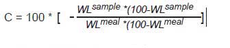
  • C = calcination rate percentage
  • WLsample = weight loss in fire (calcined meal)
  • WLmeal = weight loss in fire (raw meal)

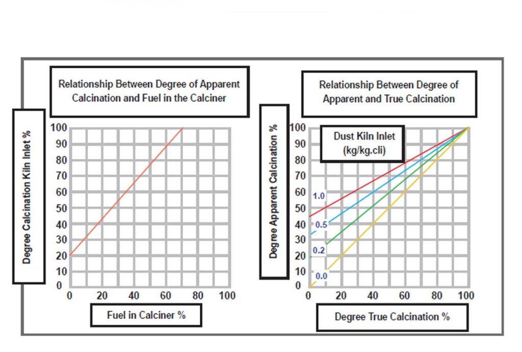
It is extremely important to understand the concepts of the degree of true calcination and the degree of apparent calcination. Degree of True Calcination is obtained when the calcination process was complete, that is, all calcium carbonate (CaCO3) was dissociated into free lime (CaO) and carbon dioxide (CO2).

Alternative fuels made from pet rubber tyres, municipal
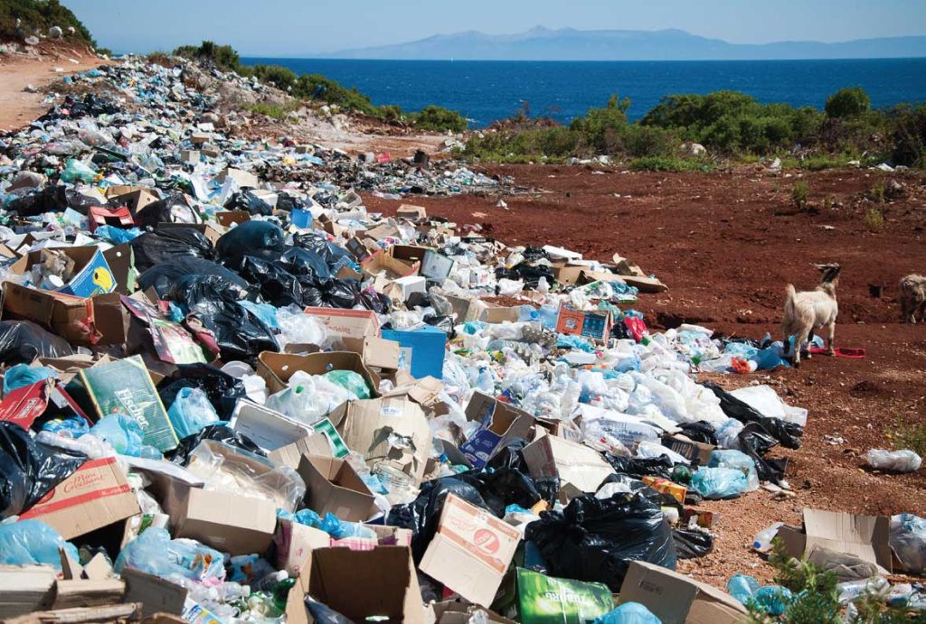
waste, clinical waste, rice husk, ground nut husk, etc.
can make pyroprocessing cost effective and help fulfil
the conditions of the Pollution Control Board.

According to this definition, we can consider two extreme cases:
Raw meal – degree of calcination = 0 per cent (weight loss in fire = 35 per cent)
Clinker – degree of calcination = 100 per cent (weight loss in fire = 0 per cent)
In this practice, we never managed to determine the true degree of calcination due to the method of collecting a sample of calcined meal extracted from the cyclone feed chute of the last stage.

As there are dust cycles in the area between the kiln, kiln inlet, gas rise duct and lower cyclone, this sample contains a certain amount of dust that was already present inside the kiln, therefore being ‘contaminated.’ This means that the collected sample contains both powders calcined by the calciner as well as extremely calcined and recycled powder from the kiln. Therefore, the degree of calcination determined with the collected sample was always to have a higher degree of calcination than with the freshly decarbonated hot meal from the calciner.

In conclusion, the degree of calcination determined according to the sample of hot meal collected in the cyclone chute feed the last stage is not a true degree of calcination plus something we call the Degree of Apparent Calcination. This means that the higher the concentration of dust near the kiln inlet area, depending on the number of dust cycles, the greater the degree of apparent calcination.

Whatever the type of calcination used, that is, a separate calciner or a calciner in-line with the kiln, it is mandatory to use a fan to process induction of the system (ID Fan), that is, the combustion gases together with carbon dioxide released in the calcination. On the other hand, in order to obtain an effective control over the secondary and tertiary air flows a control device must be used in at least one of the suction branches, for example, in the tertiary air duct.

For efficient heating of the preheater, a damper installed in the tertiary air duct prevents fresh, cold air from being diverted to the main kiln flame. However, the most important task of this damper is to obtain effective control of the oxygen rate necessary for complete combustion of fuels fed to the calciner Another form of secondary and tertiary air flow control is to install a restriction damper, normally installed in the gas riser duct. This equipment developed by some manufacturers has been used in several factories but costs more than a gate in the tertiary air duct.

ABOUT THE AUTHOR

Dr SB Hegde is currently a ‘Visiting Professor’ of Pennsylvania State University, United States of America. He has more than 30 years of experience in cement manufacturing both in India and abroad. He has occupied the ‘Leadership positions’ in reputed major cement companies both in India and overseas. He is also a recipient of ‘Global Visionary Award’ instituted by Gujarat Chambers of Commerce and Industry, Ahmedabad in 2020.

Concrete

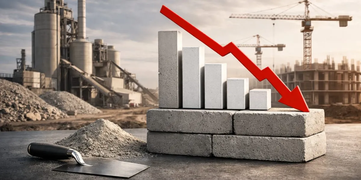
Ambuja Sees Cement Demand Easing To Around Five Per Cent In FY27

Company Cites Housing, Infrastructure And Government Capex

Published

on

By

Shares


Ambuja Cements has said in its latest annual report that cement demand in India is likely to moderate to around five per cent in fiscal year twenty seven, marking a slowdown from the estimated six point five to seven point five per cent growth anticipated for fiscal year twenty six. The company described this as a transition to a more measured pace of expansion after several years of strong momentum in the sector.

It said that underlying demand drivers such as housing, infrastructure development, urbanisation and government capital expenditure remain intact and are expected to sustain cement consumption across regions. The report noted that global geopolitical uncertainties and weather risks, including forecasts of a below normal monsoon, could influence near term demand, while emphasising that the longer term infrastructure story for India continues to provide a solid foundation for the sector.

Industry observers have said that the sector may move towards mid single digit growth rates in fiscal year twenty seven after stronger performances in recent years. The company outlined a calibrated expansion strategy with capacity additions phased to match project pipelines, regional demand patterns and market absorption, seeking to avoid oversupply and pressure on pricing.

Ambuja has crossed the 100 million tonnes per annum capacity milestone (100 mn t per annum) following acquisitions and organic expansion, strengthening its position in the competitive market. The outlook in the report broadly aligns with other market assessments that placed demand at around five per cent in fiscal year twenty five, a recovery to six point five to seven point five per cent in fiscal year twenty six and an easing in fiscal year twenty seven as capacity increases. Executives remain focused on long term demand fundamentals driven by infrastructure and housing.

Continue Reading

Concrete

Powering Cement Through Intelligent Motion

Published

on

By

Shares

Gears, drives, and motors have evolved from essential mechanical components into strategic enablers of reliability, efficiency, and sustainability in modern cement plants. ICR explores how advanced motion technologies, predictive maintenance, digitalisation, and intelligent drive systems are helping cement manufacturers reduce downtime, optimise energy use, and build future-ready operations.

As the Indian cement industry prepares for another phase of capacity expansion, the focus is shifting from merely increasing production volumes to improving operational efficiency, reliability, and sustainability. According to industry estimates, India is expected to add nearly 160–170 million tonnes of cement capacity between FY26 and FY28, driven by infrastructure investments, urbanisation, and housing demand. In this environment, gears, drives, and motors have emerged as critical enablers of productivity, forming the backbone of every major process from raw material extraction and grinding to clinker production and cement dispatch.
Motors alone account for nearly 60 per cent to 70 per cent of industrial electricity consumption globally, according to the International Energy Agency (IEA), while rotating equipment failures remain among the leading causes of unplanned downtime across heavy industries. In cement plants, where equipment operates under high loads, extreme dust conditions, elevated temperatures, and continuous-duty cycles, the performance of gears, drives, and motors directly influences energy consumption, maintenance costs, plant availability, and overall profitability. As digitalisation and Industry
4.0 technologies gain momentum, these systems are evolving from passive mechanical components into intelligent assets capable of delivering real-time operational insights.

Why gears, drives, and motors are the backbone of cement plant operations
Every major process in a cement plant depends on the seamless operation of gears, drives, and motors. Raw mills, vertical roller mills, crushers, kiln drives, conveyor systems, fans, and clinker coolers all rely on rotating equipment to maintain continuous production. A failure in any one of these systems can disrupt entire process chains, highlighting their strategic importance.
Modern cement plants process thousands of tonnes of material daily, requiring equipment capable of transmitting enormous torque while maintaining precision and reliability. Kiln drives and grinding systems, in particular, operate under some of the highest mechanical loads found in industrial manufacturing. The ability of gears and motors to withstand these conditions directly impacts plant throughput and production stability.
Satish Maheshwari, Chief Manufacturing Officer, Shree Cement says, “Effective lubrication management remains one of the most critical factors in extending the lifespan of cement plant drive systems. Proper lubrication, supported by regular oil analysis, vibration diagnostics, and condition monitoring, helps minimise wear, prevent unexpected failures, and maintain the integrity of critical components such as gearboxes, motors, and drive assemblies. By identifying potential issues at an early stage, plants can move from reactive maintenance to a more proactive and reliability-focused approach.”
“Smart motors, intelligent drives, and next-generation gearboxes are set to redefine cement plant maintenance and performance. Equipped with embedded sensors, IoT connectivity, digital twins, and AI-driven diagnostics, these technologies enable real-time condition monitoring, predictive maintenance, and seamless digital integration. As the industry embraces Industry 4.0, smart drive systems will play a pivotal role in improving energy efficiency, reducing downtime, and optimising asset performance across the cement manufacturing value chain” he adds.
Industry studies suggest that rotating equipment accounts for a significant proportion of maintenance expenditure in process industries. Effective design, selection, and maintenance of gears, drives, and motors therefore have a direct influence on asset utilisation, operational efficiency, and total cost of ownership.

The cost of downtime: reliability challenges in rotating equipment
Unplanned downtime remains one of the most expensive challenges facing cement manufacturers. Industry estimates indicate that a major failure involving a critical gearbox, kiln drive, or grinding mill can result in production losses running into lakhs of rupees per hour, depending on plant capacity and operating conditions.
Sanjeev Arora, President – Motion Business & IEC LV Motors Division, ABB India says, “One of the most significant shifts taking place in industrial decision-making today is moving away from evaluating equipment based solely on upfront capital cost toward understanding total cost of ownership (TCO). In a typical motor system, the purchase price often represents only a small fraction of the total lifecycle cost however energy consumption, maintenance requirements, downtime and operating efficiency account for the vast majority of long-term operational expenses. For cement manufacturers operating in highly competitive markets, this distinction is critical.”
“A high efficiency motor paired with an appropriately configured variable speed drive may require a higher initial investment, but the long-term benefits are substantial. Reduced electricity consumption, lower maintenance needs, longer service intervals and improved process stability can deliver faster payback and stronger profitability over time” he adds.
Cement plants present a particularly challenging environment for rotating equipment. Dust ingress, thermal fluctuations, shock loads, vibration, shaft misalignment, and lubrication contamination contribute significantly to equipment degradation. Studies by SKF indicate that nearly 50 per cent of bearing failures are linked to lubrication issues and contamination, while improper alignment and vibration-related problems remain leading causes of gearbox and motor failures.

Energy-efficient motors and drives: unlocking operational savings
Energy is one of the largest operating expenses for cement manufacturers, often accounting for 25 per cent to 35 per cent of total production costs. Grinding operations alone can consume nearly 60 per cent to 70 per cent of a plant’s electrical energy, making energy-efficient motors and drives a strategic investment.
According to the International Energy Agency, high-efficiency motors combined with Variable Frequency Drives (VFDs) can reduce energy consumption by 20 per cent to 30 per cent in suitable applications. By matching motor speed and torque to actual process requirements, VFDs minimise unnecessary power consumption while reducing mechanical stress on equipment, improving both efficiency and reliability.

Advances in gearbox design and power transmission technologies
Modern gearbox technology has evolved significantly in response to the increasing demands of cement manufacturing. Advanced materials, case-hardened gears, optimised tooth profiles, improved surface finishing, and enhanced lubrication systems are helping reduce friction, wear, and thermal loading.
Girish Hanchate, Director – Industrial Market, India SKF India (Industrial) says, “Smart diagnostics are significantly improving the lifecycle of gears, motors, and other rotating equipment by enabling a shift from reactive maintenance to condition-based asset management. Hidden issues such as vibration anomalies, bearing defects, misalignment, and temperature fluctuations can quietly reduce plant throughput by 10 per cent to 20 per cent while increasing energy consumption long before a breakdown occurs. By leveraging advanced sensors, predictive analytics, machine learning, and real-time monitoring of vibration, temperature, and motor current, cement manufacturers can detect developing faults early, optimise maintenance schedules, and prevent costly secondary damage. This not only improves reliability but also supports energy efficiency and sustainability objectives.”
“The next major evolution in drive and bearing technology lies in the development of fully integrated smart mechanical ecosystems that combine high-performance bearings, advanced lubrication management, and digital intelligence. Sensor-enabled condition monitoring embedded directly within bearings and drive systems allows operators to capture critical operational data at the source, enabling predictive maintenance and real-time performance optimisation. Innovations such as SKF’s VA9A1 Spherical Roller Bearing series, engineered specifically for demanding cement applications such as crushers and kilns, demonstrate this trend. By increasing internal bearing space and optimising lubricant flow, these designs improve grease retention, reduce wear, minimise downtime, and create more resilient, energy-efficient rotating equipment systems for the future of cement manufacturing” he adds.
Manufacturers are increasingly focusing on compact, high-torque gearbox designs capable of delivering higher power density while maintaining service life. Innovations such as condition-monitored gear systems, improved sealing technologies, and modular gearbox architectures are simplifying maintenance while enhancing operational reliability.

Predictive maintenance, condition monitoring, and asset health management
The shift from reactive to predictive maintenance is transforming asset management across the cement industry. Technologies such as vibration monitoring, thermography, oil analysis, ultrasound testing, and motor current signature analysis are enabling operators to identify potential failures before they occur.
Research by Deloitte suggests that predictive maintenance can reduce breakdowns by up to 70 per cent and lower maintenance costs by 25 per cent. In cement plants, where shutdown windows are limited and equipment operates continuously, predictive maintenance offers a powerful tool for improving reliability and extending asset life.
Digitalisation, industry 4.0, and the rise of intelligent drive systems
Industry 4.0 technologies are redefining the role of gears, drives, and motors. Smart sensors embedded within motors, bearings, and gear systems can continuously monitor temperature, vibration, load, lubrication condition, and energy consumption.
Girish Hanchate says, “As the industry embraces automation, sustainability, and digital transformation, the importance of intelligent motion technologies will continue to grow. The convergence of advanced engineering, predictive maintenance, and Industry 4.0 solutions is creating a new generation of cement plants where reliability, efficiency, and sustainability work together to deliver long-term value. For cement manufacturers navigating increasing production demands and environmental expectations, investing in smarter gears, drives, and motors is no longer optional—it is a business imperative.”
Cloud-based monitoring platforms and Industrial Internet of Things (IIoT) architectures enable maintenance teams to access equipment health data remotely, improving visibility across geographically dispersed operations. Advanced analytics and
artificial intelligence are further enhancing fault detection capabilities, enabling more accurate maintenance planning.
The emergence of digital twins represents another significant development. By creating virtual replicas of physical assets, operators can simulate operating conditions, predict failures, optimise maintenance schedules, and improve lifecycle management decisions. These technologies are helping transform rotating equipment into intelligent assets that actively contribute to operational decision-making.

Building future-ready cement plants through smart motion technologies
The future of cement manufacturing will depend heavily on the ability to integrate mechanical reliability with digital intelligence. Smart motion technologies combine high-efficiency motors,
intelligent drives, condition monitoring systems, and automation platforms to create more responsive and efficient operations.
Sustainability goals are also accelerating investment in advanced motion technologies. Reduced energy consumption, improved equipment efficiency, and extended asset life contribute directly to lower carbon emissions and reduced resource consumption.
These benefits align closely with the industry’s decarbonisation objectives.
As capacity expansions continue across India, future-ready cement plants will increasingly prioritise reliability, flexibility, and data-driven decision-making. Organisations that successfully integrate smart motion technologies into their operations will be better positioned to reduce costs, improve productivity, and maintain a competitive advantage in a rapidly evolving market.

Conclusion
Gears, drives, and motors are no longer viewed solely as mechanical components; they have become strategic assets that influence every aspect of cement plant performance. Their reliability affects production continuity, their efficiency impacts operating costs, and their digital capabilities increasingly shape maintenance and operational strategies.

  • Kanika Mathur

Continue Reading

Concrete

Liquid Intelligence

Published

on

By

Shares

Lubrication has evolved from a routine maintenance activity into a critical driver of reliability, energy efficiency, and sustainability in cement manufacturing. ICR explores how advanced lubricants, predictive maintenance, and Total Lubrication Management are helping cement plants reduce downtime, optimise performance, and achieve long-term operational excellence.

In the cement industry, discussions around operational excellence often focus on kiln efficiency, alternative fuels, digitalisation, and process optimisation. Yet one of the most influential factors affecting equipment reliability, energy consumption, maintenance costs, and sustainability often receives far less strategic attention: lubrication. From vertical roller mills and kiln drives to crushers, conveyors, clinker coolers, and large industrial gearboxes, every critical asset depends on effective lubrication to minimise friction, reduce wear, and ensure uninterrupted operation.
The importance of lubrication extends far beyond routine maintenance. According to tribology research, nearly 23 per cent of global energy consumption is associated with overcoming friction and replacing worn components. Researchers have estimated that implementing advanced tribological practices could reduce global energy consumption by as much as 8.7 per cent in the long term. For cement manufacturers operating in highly demanding environments characterised by abrasive dust, heavy loads, high temperatures, vibration, and continuous operations exceeding 8,000 hours annually, lubrication has evolved from a maintenance function into a strategic lever for reliability, sustainability, and profitability.
The significance of this opportunity becomes even clearer when viewed against the backdrop of the cement industry’s environmental challenges. According to the International Energy Agency (IEA), cement manufacturing accounts for approximately 7–8 per cent of global CO2 emissions and consumes nearly 5 per cent of industrial energy worldwide. While much attention is rightly directed toward alternative fuels, clinker factor reduction, and carbon capture technologies, maintenance practices such as lubrication remain one of the most practical and immediately deployable avenues for improving efficiency and reducing emissions.

Why lubrication is critical to cement plant reliability
Cement manufacturing relies on some of the most heavily loaded rotating equipment found in industrial production. Kiln support rollers, girth gears, vertical roller mills, crushers, conveyors, ID fans, and large gearboxes operate under extreme conditions where temperatures, loads, and contamination levels routinely challenge equipment integrity. Under such circumstances, lubricants serve not merely as friction-reducing agents but as essential protective barriers that prevent metal-to-metal contact, dissipate heat, minimise wear, and extend component life.
A modern integrated cement plant may contain thousands of lubrication points distributed across critical and auxiliary equipment. Even a minor lubrication-related issue can escalate rapidly when equipment operates continuously around the clock. Unlike batch manufacturing operations, cement plants often have limited opportunities for shutdowns, making asset reliability a key business priority. Effective lubrication directly contributes to machine availability, process stability, and production continuity.
Industry studies consistently demonstrate the relationship between lubrication and reliability. Research published by SKF indicates that approximately 36 per cent of premature bearing failures are caused by poor lubrication practices, while bearing damage accounts for nearly 50 per cent of rotating equipment failures globally. Similarly, studies by Machinery Lubrication have found that improper lubrication contributes to roughly 43 per cent of mechanical failures and more than half of bearing-related breakdowns. These statistics highlight a critical reality: lubrication is not simply a maintenance task but a reliability strategy.
The consequences of lubricant failure extend well beyond replacement parts. A failed bearing in a vertical roller mill, kiln drive, or critical conveyor system can trigger extended downtime, emergency maintenance costs, production losses, and supply chain disruptions. In large integrated cement plants, even a few hours of unplanned downtime can result in significant financial losses, making lubrication one of the most cost-effective reliability investments available.

Hidden cost of poor lubrication management
Many organisations continue to treat lubrication as a consumable expense rather than a strategic asset management function. This mindset often results in inconsistent lubrication schedules, incorrect lubricant selection, contamination issues, over-lubrication, under-lubrication, and inadequate monitoring practices. The resulting impact is often far greater than the actual cost of the lubricant itself.
Professor Procyon Mukhejee says “Lubricant purchasing often followed a conventional sourcing model: negotiate annual contracts, standardise product grades and optimise price. That logic is still relevant but no longer sufficient. In a cement plant, a lower-cost lubricant that reduces purchase spend may increase oil replacement frequency, raise wear rates or contribute to avoidable downtime. That trade-off is forcing procurement teams to think differently.”
According to industry research, up to 70 per cent of mechanical failures can be linked to contamination, improper lubricant selection, or inadequate lubrication practices. Noria Corporation estimates that world-class lubrication programmes can reduce maintenance costs by 20–40 per cent and extend equipment life by as much as 50 per cent. Conversely, reactive lubrication practices increase spare-part consumption, raise labour requirements, accelerate equipment wear, and elevate operational risk.
The hidden costs are particularly severe in cement plants because contaminants such as dust, moisture, and wear particles are ever-present. Even microscopic contaminants can damage bearing surfaces and gear teeth, leading to premature failure. Poor lubrication management also increases energy consumption because higher friction levels require greater power input to maintain production rates. As a result, the true cost of poor lubrication extends far beyond maintenance budgets and directly impacts overall plant profitability.

Lubricants and energy efficiency
Energy represents one of the largest operating expenses in cement manufacturing. Grinding operations alone account for approximately 60–70 per cent of total electrical energy consumption within a typical cement plant. Consequently, any improvement in equipment efficiency can generate substantial cost savings over time.
Lubricants contribute directly to energy efficiency by reducing friction between moving surfaces. Lower friction means less resistance, lower operating temperatures, and reduced power requirements. Advanced lubricant formulations are specifically designed to optimise film strength while minimising energy losses across gears, bearings, and hydraulic systems.
Dr SB Hegde, Global Cement Industry Expert says, “One of the most overlooked aspects of lubrication in cement plant operations is effective contamination control combined with disciplined greasing practices. Cement dust, which is often harder than bearing steel, can mix with lubricants and create an abrasive grinding paste that accelerates wear and is responsible for a significant share of bearing failures. Despite this, many plants still rely on manual, time-based greasing and outdated sealing systems, resulting in higher energy consumption, premature component wear, and frequent unplanned shutdowns. Automatic lubrication systems, coupled with robust dust exclusion measures, remain one of the most underutilised yet effective reliability solutions in the industry.”
“Smart lubrication practices can have a direct and measurable impact on both profitability and sustainability. The use of high-performance synthetic lubricants, combined with predictive oil condition monitoring, can typically deliver energy savings of 3–4 per cent, translating into substantial annual cost reductions for cement manufacturers. In one notable case, a large cement producer implemented wireless condition monitoring alongside advanced lubrication practices on critical assets and achieved a 57-times return on investment within six months. The initiative generated savings exceeding `8.4 crore and prevented a major bearing failure that could have caused more than 160 hours of downtime, highlighting the significant financial value of proactive lubrication management” he adds.
Research by ExxonMobil and other lubricant manufacturers has demonstrated that synthetic lubricants can reduce energy consumption in industrial gear systems by 2–6 per cent under appropriate operating conditions. While these savings may appear modest on an individual machine basis, the cumulative impact across multiple mills, fans, conveyors, and drive systems can be considerable. For large cement manufacturers operating energy-intensive facilities, even a 2 per cent reduction in power consumption can translate into significant annual cost savings.
Furthermore, reduced friction contributes to improved equipment performance and lower heat generation, enabling machinery to operate more consistently under demanding conditions. In an industry where energy efficiency and carbon reduction targets are becoming increasingly important, lubrication represents a practical pathway for achieving measurable improvements.

Advances in synthetic and high-performance lubricants
The lubricant industry has undergone significant transformation over the past decade. Traditional mineral oils are increasingly being supplemented or replaced by synthetic and semi-synthetic formulations engineered specifically for demanding industrial applications.
Modern synthetic lubricants provide superior oxidation resistance, thermal stability, viscosity retention, load-carrying capacity, and wear protection compared to conventional products. These characteristics are particularly valuable in cement applications where equipment is exposed to extreme temperatures, heavy loads, and continuous operation.
Many premium synthetic lubricants now deliver service lives two to five times longer than traditional mineral oils. This not only reduces lubricant consumption but also minimises maintenance interventions and associated downtime. For cement manufacturers, extended oil drain intervals can significantly improve equipment availability and reduce lifecycle costs.
Synthetic gear oils have gained widespread acceptance in applications such as kiln drives, vertical roller mills, and high-load gearboxes. Field studies have reported gearbox temperature reductions of up to 10°C following conversion from conventional lubricants to advanced synthetic alternatives. Lower operating temperatures contribute directly to improved component life, reduced oxidation, and enhanced overall reliability.

Predictive maintenance, oil analysis, and condition monitoring
The emergence of predictive maintenance has transformed lubrication from a reactive maintenance activity into a proactive asset management discipline. Rather than relying solely on time-based maintenance schedules, cement plants increasingly use oil analysis and condition monitoring technologies to assess equipment health continuously.
Oil analysis provides a wealth of information about both lubricant condition and machine health. Parameters such as viscosity, oxidation, contamination levels, moisture content, additive depletion, and wear particle concentrations can reveal developing problems long before equipment failure occurs. In many cases, lubrication-related abnormalities represent the earliest warning signs of impending mechanical issues.
Gaurav K Mathur says “Dust contamination remains the single biggest lubrication-related challenge affecting cement plant productivity today. Airborne silica and clinker dust penetrate bearings, gear housings, and lubrication systems, transforming lubricants from protective agents into abrasive mediums. These contaminants are often as hard as bearing steel and create a three-body abrasion mechanism that rapidly accelerates wear, especially under the high temperatures, shock loads, vibration, and continuous-duty operating conditions typical of cement plants. Poor sealing systems can increase wear rates by three to five times, leading to premature failures, rising maintenance costs, and reduced equipment life. Compounding the issue is a growing industry-wide shortage of experienced lubrication professionals, resulting in a loss of critical maintenance expertise and an increasing reliance on reactive rather than predictive maintenance.”
Reliability experts frequently describe oil analysis as a “blood test” for machinery because it provides valuable insights into internal equipment conditions without requiring disassembly. Studies suggest that every dollar invested in predictive maintenance can generate returns of five to ten dollars through avoided failures and reduced downtime.
Leading cement producers increasingly combine oil analysis with vibration monitoring, thermography, ultrasonic inspection, and digital condition monitoring platforms. This integrated approach enables maintenance teams to move from reactive maintenance to predictive asset management, reducing downtime while improving equipment lifespan and operational reliability.

Total lubrication management: a strategic approach to asset health
As reliability expectations continue to increase, many cement manufacturers are adopting Total Lubrication Management (TLM) programmes.
TLM extends beyond lubricant selection and incorporates every aspect of lubrication management, including storage, handling, contamination control, application methods, oil analysis, training, and continuous improvement.
Gaurav K Mathur, Director & Chief Executive, Global Technical Services says, “Smarter lubrication practices can significantly reduce both energy consumption and maintenance expenditure. The implementation of Total Lubrication Management (TLM), supported by careful lubricant selection, customised lubrication strategies, and robust contamination control, helps reduce friction across critical equipment and improve operational efficiency by up to 3 per cent. In energy-intensive cement plants, even marginal efficiency gains can translate into substantial cost savings. Improved lubrication practices also reduce wear, minimise overheating, extend equipment life, and lower the frequency of maintenance interventions, directly contributing to higher plant availability and lower total operating costs.”
“The most impactful innovation for the cement sector will not be a single lubricant product but the widespread adoption of Total Lubrication Management as a structured reliability framework. TLM integrates contamination control, oil analysis, condition-based maintenance, online filtration, lubricant regeneration, digital tracking, and condition monitoring into a unified system. This approach transforms lubrication from a routine maintenance activity into a strategic asset management function. The result is improved equipment reliability, reduced lubricant consumption, lower waste generation, enhanced energy efficiency, and a smaller carbon footprint. In an industry characterised by harsh operating environments and growing sustainability expectations, TLM offers a practical pathway to achieving higher reliability, improved profitability, and long-term operational sustainability” he adds.
One of the primary objectives of TLM is contamination control. Dust, moisture, and wear particles are widely recognised as the leading causes of lubricant degradation and equipment failure. Given the inherently dusty environment of cement plants, effective contamination control becomes essential for maintaining lubricant quality and equipment health. Another important component of TLM is lubricant consolidation. Many plants operate with dozens of lubricant grades, increasing inventory complexity and the risk of cross-contamination. Best-in-class lubrication programmes often reduce lubricant inventories by more than 30 per cent while simultaneously improving operational reliability.
Training also plays a critical role. Industry surveys suggest that fewer than half of lubrication technicians receive formal lubrication training. Yet organisations that invest in lubrication education consistently report lower failure rates, improved maintenance performance, and better asset utilisation. One widely cited industrial case study documented a reduction in bearing failures from nearly 400 per month to just 12 after implementing comprehensive lubrication excellence initiatives.

Supporting sustainability
Sustainability has become a central priority across the cement industry. While alternative fuels and carbon capture technologies often dominate discussions, lubrication also contributes significantly to environmental performance.
Longer-lasting lubricants reduce waste oil generation and disposal requirements. Large integrated cement plants may consume tens of thousands of litres of lubricants annually, making lubricant lifecycle management an important sustainability consideration. Extending drain intervals by even 50 per cent can substantially reduce lubricant consumption and associated environmental impacts. Improved lubrication also extends equipment life, reducing demand for replacement components and lowering the environmental footprint associated with manufacturing, transportation, and installation activities. By reducing friction and wear, lubricants enable machinery to operate more efficiently while consuming less energy.
Tribology researchers Holmberg and Erdemir estimate that advanced friction-reduction technologies could potentially reduce global carbon emissions by up to 1,460 million tonnes annually. Although this figure spans multiple industrial sectors, it
highlights the enormous sustainability potential of improved lubrication practices. For cement manufacturers pursuing net-zero ambitions, lubrication represents one of the most accessible and cost-effective tools available.

Digitalisation, automation, and smart monitoring
The future of lubrication management is increasingly digital. Smart sensors, Industrial IoT platforms, automated lubrication systems, and artificial intelligence are changing how maintenance teams manage equipment health.
Modern lubrication monitoring systems can continuously track temperature, viscosity, moisture levels, contamination levels, and lubricant condition in real time. This enables maintenance personnel to identify emerging issues before they affect production, allowing interventions to be planned rather than forced by equipment failures.
“The future of lubrication management will be defined by the integration of smart, data-driven, and automated systems powered by IoT sensors, artificial intelligence, and real-time oil condition monitoring. These technologies are enabling a shift from traditional schedule-based lubrication to predictive and prescriptive maintenance, where lubricant quantity, frequency, and selection are optimised based on actual equipment condition. The result will be near-zero unplanned downtime, lower lubricant consumption, higher equipment reliability, and improved Overall Equipment Effectiveness (OEE). As India continues to add significant cement manufacturing capacity, early adopters of intelligent lubrication technologies will gain a competitive advantage through lower operating costs, greater reliability, and stronger sustainability performance” says Dr Hegde.
Automated lubrication systems are also becoming more prevalent throughout the cement industry. By delivering precise lubricant quantities at predetermined intervals, these systems eliminate many of the inconsistencies associated with manual lubrication practices. The result is improved equipment protection, lower lubricant consumption, and enhanced reliability.
Market analysts forecast the global predictive maintenance market to exceed $50 billion by 2030, reflecting the growing importance of data-driven maintenance strategies. As digital technologies continue to mature, lubrication will become an increasingly integrated component of broader asset performance management systems.

Conclusion
As cement manufacturers pursue greater productivity, higher sustainability standards, and improved operational resilience, lubrication must be recognised as a strategic business function rather than a routine maintenance activity. The evidence is overwhelming: effective lubrication improves reliability, reduces energy consumption, extends equipment life, lowers maintenance costs, and supports sustainability objectives simultaneously.
The next frontier of cement plant optimisation will not be driven solely by larger kilns, more efficient mills, or alternative fuels. It will also be shaped by how effectively operators manage the health of their critical assets. Through advanced lubricants, predictive maintenance, oil analysis, contamination control, and Total Lubrication Management programmes, cement manufacturers can unlock substantial gains in operational performance while supporting long-term environmental and business goals.
In an increasingly competitive industry, lubrication is no longer merely about reducing friction. It is about enabling reliability, protecting profitability, and creating a foundation for sustainable growth. The plants that recognise this shift and invest in lubrication excellence today will be best positioned to meet the performance demands of tomorrow.

Continue Reading

Video Thumbnail

    SIGN-UP FOR OUR GENERAL NEWSLETTER


    Trending News

    SUBSCRIBE TO THE NEWSLETTER


    Don't miss out on valuable insights and opportunities to connect with like minded professionals.


      This will close in 0 seconds