Switching from traditional screw pumps to advanced rotary airlocks can dramatically cut energy use in pneumatic conveying.
Pneumatic conveying is a clean, quick and reliable way of moving materials around the plant. Ideal for both fine and coarse-grained materials, pneumatic conveying lines can be installed almost anywhere they are needed around cement plants and terminals, with much greater flexibility in terms of layout than their mechanical alternatives. High, low, bending left or right, they can adapt to your needs, enabling you to fit a new line into even the busiest sites. The enclosed pipe ensures no dust escapes to the local environment, keeping your plant clean and reducing the maintenance burden that comes from contaminants getting into machinery. The maintenance needs of the systems themselves are also low because there are very few moving parts, which gives you excellent availability as well as maximum peace of mind. And the capacity to convey at high pressures ensures you have ample throughput to meet the demands of your process.
All this adds up to a very low total cost of ownership compared with mechanical conveying, where the maintenance needs and associated productivity losses are much higher, and the flexibility is much lower. The result is that pneumatic conveying is almost always the most efficient means of transporting materials around a site.
In those instances where pneumatic conveying does not look like an efficient option, the reason is typically given as high energy consumption. However, the introduction of a new rotary airlock, the V-Series Airlock/Feeder, reduces the installed power of pneumatic conveying systems and lowers operating costs significantly.
Finding a more energy efficient feed system
Historically, the screw pump has been the preferred means of feeding pneumatic conveying lines. With more than 100 years experience, it is a proven technology and one that is still highly applicable for many conveying applications transporting fine, dry materials. But while the system is flexible in terms of capacity and layout, it can be beaten on energy efficiency by a rotary airlock. The following case studies illustrate two such examples.
Case study 1
Table 1 shows the details of the energy requirement for a cement plant s pneumatic conveying system with screw pump. This plant was using a pneumatic conveying system to transport raw meal to the preheater tower. To reduce the energy load for this operation, the plant wanted to explore alternatives to the screw pump line charger. We introduced them to the new V-Series rotary airlock.
V-Series rotary airlock
The V-Series is a 10-vein rotary airlock designed to handle dry, fine powder or granular product at high-pressure differentials up to 29 psig (2 bar) in dense phase or dilute phase systems. It requires much less power on the drive motor, generating a significant energy saving, and it is more flexible in terms of the materials it can handle, giving plants the ability to transport a wider range of materials. In cement plants, the V-Series is typically used to transport cement kiln dust, cement, fly ash, pulverised coal and pet coke. In cement terminals, applications include unloading from railcars to storage silos, discharge from storage silos to use bins, loadout and packing systems.
Abrasion
Abrasive wear is a concern when operating rotary feeder/airlocks handling abrasive materials. Conventional feeder/airlocks are limited to lower pressure operation. However, this can be counteracted using specialist ceramic and tungsten carbide coatings on the rotor and feeder veins with the V-series feeder/airlock, which allows us to handle more abrasive materials at higher pressures.
Reduced energy consumption
Table 2 shows the significant reduction in installed power required with the V-Series at just 6 hp compared with 350 hp for the screw pump. This was the energy requirement for two airlocks, as were needed in this case, with each having an installed power of just 3 hp. This translates to an overall savings in total installed power of 32 per cent for the entire system and a reduction in operating costs of US$160 000 (Table 3), giving the plant a swift ROI of less than one year.
Case study 2
Figure 1 shows an old screw pump at a cement terminal in the US. The terminal operators wanted to repurpose the old silos for red masonry cement, which they needed to store separately to prevent product contamination. They requested that we put in a system that replaced the old screw pump but maintained the existing 12 in. x 24 in. rotary cut-off valve shown in the picture. The role of the airlock was to discharge masonry cement from the silo to a packing bin at a rate of 50 stph in an 8 in. pipeline, measuring 200 ft. long with five 90 elbows.
The system we designed is shown in Figure 2. We successfully installed the new V-Series airlock within the allotted space and achieved the desired capacity. The new system runs at 12 rpm, using the same air supply, which was 1400 sfcm at 18 psig. The Airlock is installed with a variable speed drive set to operate at between 5 and 30 rpm using a VFD drive, giving the terminal operators optimum efficiency.
This installation proves the flexibility of the system, which can be retrofitted into small spaces and replace outdated technology.
Conclusion
Significant energy savings and long-term reductions in operating costs can be achieved with a relatively straightforward switch from a screw pump to a V-Series airlock. For new conveying systems, the V-Series airlock is an energy efficient choice to help cement plants achieve their sustainability goals.
Sidebar: How does pneumatic conveying work?
A typical pneumatic conveying system runs what is known as two-phase conveying. This is a mix of dense and dilute phase conveying, in which the pipe is divided into a top half and a bottom half. Along the bottom, materials move relatively slowly. This is the dense phase. Along the top, you have fewer materials more widely dispersed in the dilute phase. These particles have been picked up by the conveying air and are almost flying along at a high velocity. As they lose velocity, they will drop out of the dilute phase and join the dense phase below. But, as the materials accumulate along the bottom of the pipe, the cross-sectional area through which air can move narrows and velocity increases again, allowing the conveying air to pick up particles and move them along at high velocity. This cycle repeats, giving a kind of wave formation in the materials along the bottom of the pipe.
Sidebar: Upgrading old systems
In the case of the cement terminal, switching from a screw pump to an airlock brought about greater efficiency and this is often the case for this kind of upgrade. However, it should be noted that in some instances when converting an old screw pump system to a rotary airlock, efficiency can be lost if displaced air needs to be compensated by increasing horsepower to the compressor or blower to an extent that the power savings on the airlock are cancelled out. For this reason, it s essential to check the existing system thoroughly before assuming that an upgrade will result in energy savings.
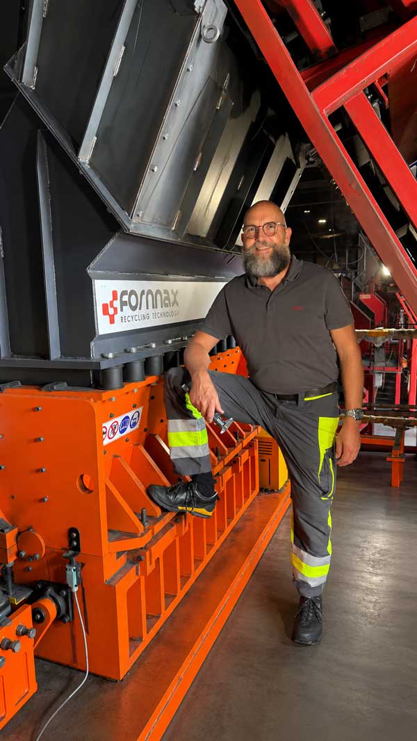
Strapline: Fornnax Technology has appointed NOBA Maschinenservice’s Lukas Baur as its authorised service partner for the European Union, strengthening its commitment to delivering fast, reliable, and localised after-sales support across the region.
Fornnax Technology, a leading manufacturer of industrial shredding solutions, has announced the appointment of Mr. Lukas Baur of NOBA Maschinenservice as its authorised service partner for the European Union. The partnership, formalised under the authorisation of Fornnax CEO Mr. Jignesh Kundaria, reinforces the company’s commitment to providing dependable, localised service support to its expanding customer base across Europe.
Strengthening Service Through Proven Expertise
With over two decades of experience in servicing, maintaining, and overhauling industrial shredders, Mr. Baur brings extensive technical expertise to the partnership. His capabilities span welding, hardfacing, shaft and knife rebuilding, complex assembly, hydraulics, and complete electrical engineering services, delivered in collaboration with a trusted partner company based in Halle/Saale.
Operating from Worbis, Germany, Mr. Baur is strategically positioned to provide emergency support across the European Union within 24 hours, covering an operational radius of approximately 1,000 kilometres.
Supporting this capability is a well-equipped service infrastructure comprising 12 Mercedes Sprinter service vans, a team of 24 skilled technicians, specialised bearing-change tools, a fully equipped hydraulic workshop, and a 1,000-square-metre facility with a five-ton crane track. Together, these resources position his team to manage the complete spectrum of Fornnax’s European service requirements efficiently and reliably.
Partnership Driven by Industry Insight
Having spent years servicing Eldan, Lindner, and Vecoplan shredders across the European recycling industry, Mr. Baur’s decision to collaborate with Fornnax is rooted in his understanding of market needs and customer expectations. His experience has provided valuable insight into what recycling plant operators require—not only from their machinery but also from the service teams supporting them.
According to Mr. Baur, Fornnax’s reputation for robust machine construction, superior wear protection, and maintenance-friendly design made the partnership a natural fit.
The collaboration comes at a time when Europe’s tyre recycling industry is facing mounting challenges, including rising cost pressures, shrinking margins, delayed investments, and a shortage of skilled labour. Mr. Baur believes these conditions reinforce the need for technically strong service partners capable of delivering rapid, dependable support.
Commenting on the partnership, he said, “Fornnax, with its exceptional price-performance ratio and superior quality, has the potential to become a market leader in Europe. We would like to be their service partner in this journey.”
Comprehensive Support Across the Equipment Lifecycle
As Fornnax’s authorised service partner, Mr. Baur will oversee the complete lifecycle support of the company’s equipment throughout the European Union. His responsibilities will include installation, commissioning, preventive maintenance, emergency repairs, and spare parts support across mechanical, hydraulic, and electrical systems.
Looking ahead, he also plans to develop a centralised spare parts distribution hub for European customers, particularly if Fornnax establishes a warehouse facility in Worbis to facilitate faster deliveries. To further strengthen service coverage, Mr. Baur intends to expand operations by adding two to three additional service teams and vehicles each year, progressively increasing capacity across the continent.
A Shared Commitment to Customer Excellence
Highlighting the strategic importance of the partnership, Mr. Jignesh Kundaria, Director and CEO of Fornnax, said:
“We strongly believe that by continuously improving our service quality and customer satisfaction index, we can build long-term relationships with our customers. Higher customer satisfaction leads to greater trust, which significantly increases repeat orders and ultimately drives sustained growth in our sales revenue.”
This customer-first philosophy underpins Fornnax’s strategy of building a dedicated European service partner network instead of relying solely on remote support. With Mr. Baur joining this network, customers across the European Union will benefit from faster response times, expert technical assistance, and dedicated on-ground support from a partner with extensive experience in high-throughput shredding operations.
Mr. Baur’s appointment also reflects Fornnax’s broader ambition to establish itself as the preferred shredding solutions provider for the European recycling industry, marking another important milestone in the company’s international growth strategy.
Nuvoco Vistas opens a 2 MMTPA grinding unit at Limla, entering Gujarat and advancing its target of 35 MMTPA capacity by FY 2028.
Surat (Gujarat)
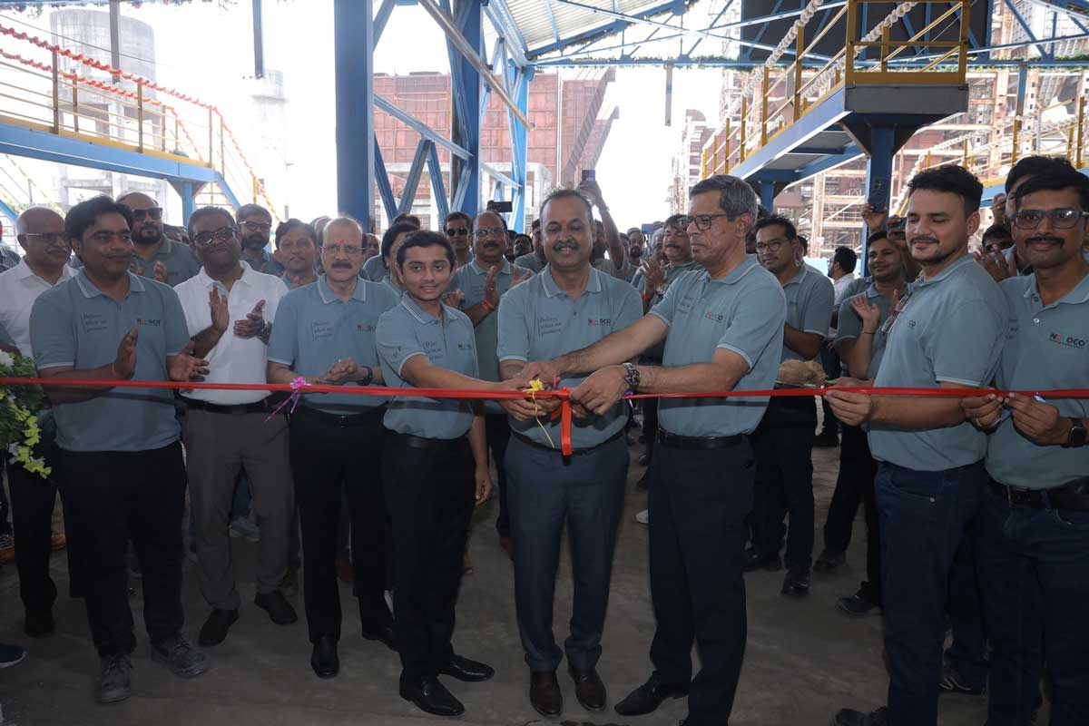
Nuvoco Vistas Corporation Ltd, a part of Nirma Group and one of India’s leading building materials company, has inaugurated the Limla Cement Plant in Surat (Gujarat), one of Vadraj Cement Limited’s (VCL) principal manufacturing facilities. The commissioning represents a key milestone in Nuvoco’s acquisition and restoration of VCL, while supporting the company’s expansion across the Western Indian cement market.
Vadraj Cement Limited is a subsidiary of Nuvoco Vistas Corporation Limited and has installed cement capacity of 6 MMTPA across its assets. The Limla inauguration therefore represents the first operational step in the acquired platform’s wider revival, while the Kutch facilities provide clinker supply, mineral security and coastal logistics support for the western business.
Nuvoco completed its acquisition of Vadraj Cement Limited, then under the Corporate Insolvency Resolution Process, after paying a consideration of Rs 1,800 crore in June 2025. VCL’s asset portfolio comprises a clinker unit at Kutch and a grinding unit at Limla in Surat. It also includes high-quality captive limestone reserves and a captive jetty at Kutch, supporting more efficient logistics. Following the takeover, Nuvoco began an extensive programme of restoration, refurbishment and expansion at both locations, leading to the commissioning of the Limla plant.
The Limla Cement Plant is expected to support a phased increase in sales volumes across Gujarat. It will also help Nuvoco supply neighbouring markets in Western Maharashtra and release cement capacity from its northern plants, which can consequently be redirected towards markets in North India. The plant will manufacture a full portfolio comprising Ordinary Portland Cement, Portland Slag Cement, Portland Pozzolana Cement and Portland Composite Cement. It will additionally produce the complete Nuvoco Duraguard range, including the premium Nuvoco Duraguard Microfibre product. The acquisition is also expected to generate operational synergies with Nuvoco’s existing plants at Nimbol and Chittorgarh in Rajasthan, improving logistics optimisation and market reach across important regional markets.
The grinding unit at the Limla Cement Plant was completed ahead of schedule, with 2 MMTPA of capacity now inaugurated to expand Nuvoco’s operating scale and customer reach. After Vadraj Cement’s assets become fully operational, plants in North and West India are expected to account for nearly 40 per cent of Nuvoco’s total cement capacity. This will broaden the company’s manufacturing network, strengthen access to high-growth markets and support its plan to increase consolidated cement capacity to 35 MMTPA by FY 2028, reinforcing its longer-term growth strategy.
Commenting on the development, Jayakumar Krishnaswamy, Managing Director, Nuvoco Vistas Corp Ltd, said: “The inauguration of the Limla Grinding Unit in Surat is an important milestone in Nuvoco’s growth journey and demonstrates our commitment to disciplined, value-accretive expansion. Gujarat is strategically significant for Nuvoco, with substantial opportunities arising from infrastructure investment, industrial growth, rapid urbanisation and continuing demand from the housing and construction sectors. The facility strengthens our regional footprint, improves operational flexibility and increases our ability to serve customers across northern and western markets with greater reliability and efficiency.”
He added: “Through the Vadraj acquisition, we have refurbished and restarted a strategically important asset, returning it to operations in record time through strong execution and collaboration between teams. The achievement demonstrates our ability to create value from acquired assets, fulfil our commitments and retain the confidence of stakeholders. It also highlights the strength of our project delivery capabilities and our continued focus on building sustainable, profitable growth over the long term.”
Nuvoco Vistas Corporation Limited is a building materials company whose vision is to build a safer, smarter and more sustainable world. It is among the leading players in East India and has a significant presence across North and West India. Nuvoco began operations in 2014 with a greenfield cement plant at Nimbol, Rajasthan. It later acquired Lafarge India Limited, which had entered India in 1999, followed by Emami Cement Limited in 2020 and Vadraj Cement Limited in April 2025. The company has also announced an expansion in eastern India through a new grinding mill at the Arasmeta Cement Plant, supported by several debottlenecking programmes involving equipment upgrades, process improvements and internal capacity initiatives. These developments place Nuvoco on track to achieve total cement capacity of approximately 35 MMTPA. The company reported total income of Rs 11,362 crore in FY 2025-26, reflecting its continuing growth trajectory.
Nuvoco operates a diversified portfolio across three segments: Cement, Ready-Mix Concrete and Modern Building Materials. Its cement portfolio includes Concreto, Duraguard, Double Bull, PSC, Nirmax and Infracem, covering Ordinary Portland Cement, Portland Slag Cement, Portland Pozzolana Cement and Portland Composite Cement. Its pan-India RMX business provides value-added products under Concreto for performance concrete, Artiste for decorative concrete, InstaMix for ready-to-use bagged concrete, X-Con covering M20 to M60 grades, and Ecodure for specialised green concrete. Nuvoco has supplied materials to projects including the Mumbai-Ahmedabad Bullet Train, Birsa Munda Hockey Stadium in Rourkela, Aquatic Gallery at Science City in Ahmedabad, and metro railway projects in Delhi, Jaipur, Noida and Mumbai.
Indian Cement Review (ICR) and Fuller Technologies brought industry, policy and technology leaders together to discuss how cement innovation can drive green construction at scale, writes Rakesh Rao.
India is building at a pace few countries can match. Highways, airports, housing, logistics parks, industrial corridors and urban infrastructure are reshaping the country’s economic geography. But beneath this growth story lies a difficult question: can India continue to build at scale without locking itself into a high-carbon future?
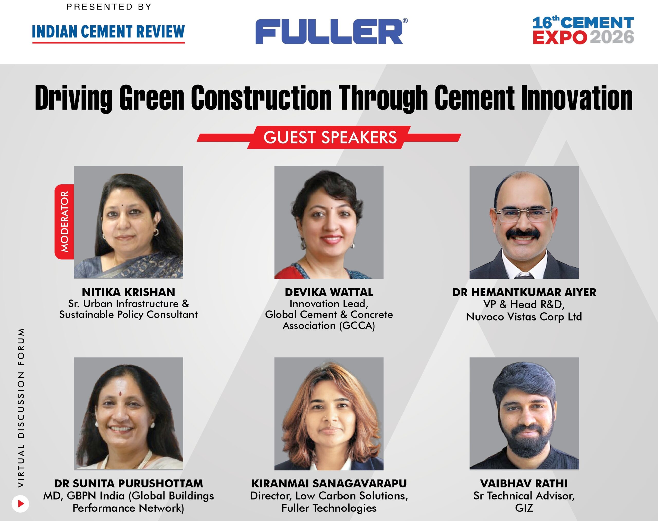
That question formed the core of an online panel discussion titled “Driving Green Construction Through Cement Innovation”, organised by Indian Cement Review (ICR) in association with Fuller Technologies as the Presenting Partner on June 25, 2026. The webinar brought together experts from cement technology, R&D, global industry platforms, building performance policy and international development cooperation to examine how low-carbon cement and material innovation can accelerate India’s green construction transition.
The discussion came at a crucial time. India has committed to achieving net-zero emissions by 2070 and reducing the carbon intensity of its economy by 45 per cent by 2030. At the same time, the country’s construction sector is expanding rapidly, driven by urbanisation, infrastructure development, housing demand and industrial growth. Cement, as one of the most widely used construction materials, sits at the heart of this transition. It is indispensable to development, but also central to the challenge of reducing embodied carbon in buildings and infrastructure.
Moderated by Nitika Krishan, Senior Urban Infrastructure and Sustainable Policy Consultant, the panel featured:
Dr Hemantkumar Aiyer, VP and Head R&D, Nuvoco Vistas Corp Ltd;
Devika Wattal, Innovation Lead, Global Cement and Concrete Association (GCCA);
Dr Sunita Purushottam, MD, GBPN India (Global Buildings Performance Network); and
Vaibhav Rathi, Senior Technical Advisor, GIZ (the German Agency for International Cooperation)
Setting the tone for the discussion, Nitika Krishan underlined the scale of the challenge before the sector. “The question before us is no longer whether we build, but how we build sustainably,” she said. She pointed out that construction accounts for nearly 40 per cent of global energy-related carbon emissions when both operational and embodied carbon are considered. Cement production, she added, remains one of the hardest industrial processes to decarbonise.
For India, this is not merely an environmental issue. It is a development issue, a competitiveness issue and increasingly, a market issue. As one of the world’s largest cement producers and among the fastest-growing construction markets, India’s material choices will influence the carbon trajectory of its built environment for decades. As Krishan observed, sustainability solutions in economies such as India must not remain limited to laboratory success. They must be scalable, commercially viable and practical at national level.
The innovation gap: From technology to market
Experts believe that there is a need to bridge the innovation gaps for making decarbonisation in cement and concrete scalable. Devika Wattal of GCCA, explained, “The starting point must be the core cement manufacturing process itself. The first and foremost is the heart of our process, the heart of cement manufacturing. How do we reduce clinker? That is always a topic where industry is working very intrinsically.”
Clinker reduction remains one of the most important pathways for lowering emissions in cement. Since clinker production is energy-intensive and chemically emits carbon dioxide, reducing the clinker factor through supplementary cementitious materials (SCMs), blended cements and new chemistries can have a significant impact. Wattal also noted that carbon capture, utilisation and storage (CCUS) will have a role, though it may not be the first lever for all markets.
However, she stressed that innovation cannot stop at technology development. A solution that works in the lab must also be adaptable to industry, scalable in production and acceptable in construction practice. “It is important for that innovation to be adaptable, to be scalable, and so that it can be executed in real time,” she said.
Wattal also called for stronger enabling systems around innovation. These include performance-based standards, product-level embodied carbon databases and clearer frameworks for evaluating green materials. Without these, low-carbon cement products may struggle to compete with conventional materials in procurement and design.
R&D must balance carbon, cost and performance
Bringing in the R&D perspective into the discussion, Dr Hemantkumar Aiyer of Nuvoco Vistas emphasised that low-carbon cement development cannot be treated as a single-variable exercise. Cement must perform in real construction conditions. It must deliver strength, durability, consistency and cost competitiveness, while also reducing carbon.
“The root of understanding and balancing all these aspects lies in materials, and knowing the materials,” he said.
According to Dr Aiyer, R&D teams must understand the variability of raw materials such as fly ash, slag and clinker. Different sources produce different material behaviours. This makes mix optimisation, material characterisation and processing-property relationships critical. When performance is affected, cement manufacturers must understand how strength enhancers, admixtures and other performance chemicals interact with the material system.
He also linked material science with process efficiency. Clinkerisation takes place at extremely high temperatures, around 1,400 to 1,450 degrees Celsius. Any improvement in raw mix design, process control or energy optimisation can, therefore, help reduce emissions and cost. Dr Aiyer pointed to artificial intelligence-based optimisation, Cement 4.0 tools and advanced software as important enablers for real-time process and material control.
“The more you understand the materials, the more you can control it,” he said.
LC3: The promise is proven, the sequencing is not
Limestone calcined clay cement, commonly referred to as LC3, has attracted global attention because it can reduce clinker content significantly by using calcined clay and limestone while maintaining performance in many applications. Kiranmai Sanagavarapu of Fuller Technologies said the technology itself has already moved beyond proof of concept. Fuller Technologies has worked with calcined clay technology for nearly two decades and has seen plants running in France and Ghana. These plants, she said, are meeting local and national specifications, while the economics are beginning to make sense.
“The calciner is performing, the economics is stacking up, it is making business sense to produce,” she said.
But if the technology is viable, why has adoption not scaled faster? For Sanagavarapu, the answer lies in project sequencing. Too often, clay characterisation happens after equipment is specified. This, she warned, is a backward approach because calciner design depends on clay mineralogy, kaolinite content, iron levels, reactivity, moisture and other variables.
“If you don’t know what your deposit looks like before you commit for the equipment, you are, in a way, going blind into designing,” she said.
She also identified permitting and plant integration as major bottlenecks. Environmental clearances, mining permissions and local regulatory approvals must begin early. Similarly, calcined clay must be integrated into existing grinding, blending and logistics systems from the design stage, not treated as an afterthought during commissioning.
India already has IS 18189:2023 standard for LC3, but Sanagavarapu pointed out that the standard is not yet visible enough in procurement documents. “The gap between what is technically being permitted and what the procurement is asking is the single biggest bottleneck,” she said.
In her view, successful scale-up depends on getting the sequence right: clay characterisation first, permitting in parallel, standards aligned with construction, and integration built into plant design.
India’s LC3 journey: Progress, but demand remains thin
Providing details of India’s LC3 commercialisation experience, Vaibhav Rathi of GIZ noted that JK Cement carried out the first commercial production of LC3 at its Rajasthan plant, followed by JK Lakshmi Cement three months later. These initiatives were supported by the International Climate Initiative of the Government of Germany, with IIT Delhi contributing deep institutional knowledge on LC3 research and BIS certification.
Rathi said India’s early experience has produced clear lessons. One of the biggest was the need to build capacity among regulators. While BIS certification existed, State Pollution Control Boards were unfamiliar with the technology and unsure about the approval pathway.
“The capacity building is not just needed amongst the producer and the users of the cement, but also the regulators who are working with this technology for the first time,” he said.
He also highlighted the need for better information on China clay deposits. Since China clay is currently classified as a minor mineral, centralised data on availability, quality and location is limited. If cement manufacturers are to adopt LC3 at scale, stronger mineral intelligence will be important.
The third issue is demand. LC3 has already been used in projects such as Palava City in Mumbai and Noida International Airport, but these remain limited examples. “It is in a chicken and egg situation,” Rathi said. “Cement companies are saying we need more demand, and users are saying there is not enough cement available.”
Public procurement, he suggested, could help break this cycle. If agencies such as CPWD and other public bodies begin testing, accepting and specifying LC3, it could create the market confidence needed for cement companies to invest in production and storage.
Building codes must catch up with innovation
Dr Sunita Purushottam of GBPN India argued that material choices will determine built environment emissions over the long term, but India’s current policy signals remain fragmented. Although LC3 has received BIS recognition, she pointed out that building codes, municipal bylaws, schedules of rates and sustainability codes do not yet provide uniform guidance on low-carbon cement.
“The current cement regulations are largely prescriptive and favouring traditional materials,” she said. This limits the ability of alternative materials to compete on performance, durability and emissions.
Dr Purushottam also raised the issue of taxation. Cement, including LC3, currently falls under the same GST bracket as conventional cement. A differentiated tax structure, she argued, could help accelerate market adoption. “In order for the market to demand LC3, that differentiation in the GST could go a long way,” she said.
She noted that green building certifications such as IGBC and GRIHA are already creating demand for low-carbon materials by assigning points for embodied carbon and sustainable material use. However, she said large-scale adoption will require regulatory mandates, particularly through building codes and state-level notifications.
She also cautioned that low-carbon cement alone does not solve the entire building performance problem. A material may reduce embodied carbon, but the operational carbon of a building depends on thermal performance, design, insulation and energy use. “The energy part has two elements,” she said. “One is the embodied carbon of the material itself, and the other is the operational carbon.”
Collaboration is the bridge between invention and impact
Wattal said GCCA sees innovation as a strategic priority and works through platforms that connect industry with academia and start-ups. “There is no way we will decarbonise our sector without innovation,” she said.
However, she stressed that research must be connected to actual industry challenges. Innovations developed in isolation may fail when they encounter real-world barriers such as raw material variability, plant integration, cost, standards and finance. Start-ups, too, need industry mentorship and scale-up pathways.
Wattal also flagged the importance of finance. Even strong technologies may struggle to attract investment if there is no common understanding of bankability. “We have always put projects into, is this a bankable project? But the definition of a bankable project has never been defined,” she said.
For India, she saw strong potential in its academic and start-up ecosystem, but said the challenge lies in alignment and prioritisation. The country has the research base, industrial capacity and market size. What it now needs is a coordinated route from innovation to deployment.
There is a practical concern for cement manufacturers: how can existing plants be adapted for lower emissions without compromising reliability or commercial viability?
Kiranmai Sanagavarapu addressed, “The reliability risk in calcined clay retrofit is definitely real, but it is almost always self-inflicted. The risk arises when a new process is added to an existing circuit without properly redesigning grinding and blending configurations.”
Existing cement plants, she explained, can take two broad routes. The first is external sourcing of calcined clay combined with mill optimisation. This requires lower capital investment and can potentially move in 12 to 18 months if other conditions are in place. It may reduce emissions by around 20 to 30 per cent. The second route is integrated calcination on site, which requires higher capital expenditure and longer lead times, but provides greater control over quality, supply and emissions reduction potential.
For Sanagavarapu, the principle is simple: low-carbon retrofits must be designed with intent. “Design it with an intent properly from the start. Start in the market conditions where the economics are already working,” she said.
Circularity: The overlooked advantage
According to Vaibhav Rathi, fly ash and slag are already well established in cement and construction (C&D), but construction and demolition waste remains underutilised. “C&D waste is a growing business opportunity which not many have taken up,” he said. India’s continuous construction and demolition activity creates huge volumes of waste, much of which contributes to air pollution, land degradation and material inefficiency. With the right processing and standards, this waste can be converted into useful construction products.
Rathi also pointed out that LC3 has a circular economy dimension that is often overlooked. It can use low-grade kaolin-rich clay left behind after high-grade clay is extracted for other applications. “LC3 is not only a low-carbon solution, but also a circular economy solution,” he said.
At the same time, he cautioned that LC3 in India is not yet cheap because it has not reached scale. Site-specific techno-commercial feasibility studies, supported jointly by development agencies and industry, could help companies assess whether LC3 production makes technical and financial sense at a given location.
Dr Purushottam added that India must address both low-carbon cement and construction waste together. “Both low-carbon cement and C&D waste go hand in hand. India does not have an option but to work on both,” she said.
Dr Aiyer called for policy shifts from both government and industry, including preferential purchasing of sustainable materials, minimum supplementary cementitious material requirements in public and public-private projects, and faster regulatory implementation. “If we can fast-track the regulatory standards and their implementation on the ground, that is the way to go,” he said.
From green ambition to green construction
Cement innovation is no longer only about chemistry. It is about systems. Low-carbon cement will scale only when technology, standards, procurement, finance, regulation, education and construction practice move together.
LC3 and other low-carbon technologies have shown promise. India has early commercial examples, strong research capability and growing market interest. But mainstream adoption will depend on whether demand can be created, regulators can be capacitated, standards can be embedded in procurement, and manufacturers can see a clear business case.
For a country building at India’s scale, the opportunity is enormous. Cement will continue to be central to infrastructure and urban development. The challenge now is to ensure that the cement used in India’s growth story carries a lower carbon burden.
Rakesh Rao
Participate in Cement Expo 2026 and discover how next-gen infrastructure can be built with innovations in cement.


 Concrete4 weeks ago
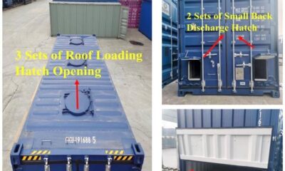
 Concrete4 weeks ago
 Concrete3 weeks ago
 Concrete3 weeks ago