Connect with us

Concrete

Refractories: ‘Tech’ing Up!

Published

on

Shares

Refractory failure is considered the most critical upset in a kiln operation. Considering the importance of refractories in the cement making process, ICR delves into the various types of refractories, their operations, challenges and the efforts taken by cement manufacturers in keeping up with innovations and automation of refractories for more efficient processes.

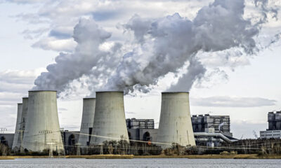
Cement is the most consumed man-made product across the globe. The modern civilisation owes a lot to the contribution of cement and concrete as a building material for construction of bridges, buildings, roads, dams, tunnels, and tall structures which are being used by the people everywhere in every walk of life. Manufacturing process of cement involves high temperatures. The combustion of limestone, clay or other materials to form clinker is an extremely energy intensive and temperature intensive process. This high-temperature reaction takes place inside a reactor called a kiln.

To contain the temperature inside the kiln on a continuous basis and to make the manufacturing possible on an industrial scale, Refractories play a very important role. A refractory lining inside the reactor maintains the temperature range of the reactor metal structure within a tolerable limit. This lining, also known as refractory, also inhibits the heat flow from inside of the reactor to outside. Thus, it helps in conserving the energy, which makes the cement manufacturing process productive and profitable.

There are two major purposes of refractories in a cement manufacturing unit:
To contain the high temperature or heat generated during pyroprocessingTo insulate the reactor and prevent the heat from dissipating in the environment

The special demands of cement manufacturing have always required specialised refractories – especially now, when more and more alternative fuels are used.

Types of Refractories

The special demands of cement manufacturing have always required specialised refractories – especially now, when more and more alternative fuels are used. There are two main types of refractories: castable and brick, each with distinct advantages and disadvantages.

Castable Refractory: This refractory comes in a powder form and is mixed with water on-site. Before the mixture can be put in place, anchors are installed. These Y-shaped anchors are similar to rebar in cement; they help give the castable lining its strength. Once these anchors are in place, the cement-like mixture is pumped into the lining of the rotary kiln, and allowed to cure for several days.

Brick Refractory: Brick is fired in a furnace under tightly controlled conditions that allow it to achieve better properties than a similar composition castable refractory.

Castable refractory has a similar material cost to brick. However, brick installation is much more labor intensive, as each brick is individually installed. This makes the overall cost of a brick lining more expensive than castable. While brick refractories are slightly more expensive than castable refractories, bricks do not require anchors, and their quality is superior. When processing a highly abrasive material, brick refractory is advisable most of the time, as castable does not have the durability to stand up against abrasive materials as well as brick.

Besides lower overall cost, the advantage to using a castable refractory in a rotary kiln is that it is usually easily patched when a problem is encountered. Down time is typically minimal, because the problem area can be cut out and new refractory poured into the cavity.

The disadvantage to using a castable refractory in a rotary kiln is that it is very susceptible to installation problems. When a castable refractory is expertly installed, it can nearly match the quality of brick.

But if installed incorrectly, there can be a considerable difference in quality, and the life of the refractory can be severely compromised.

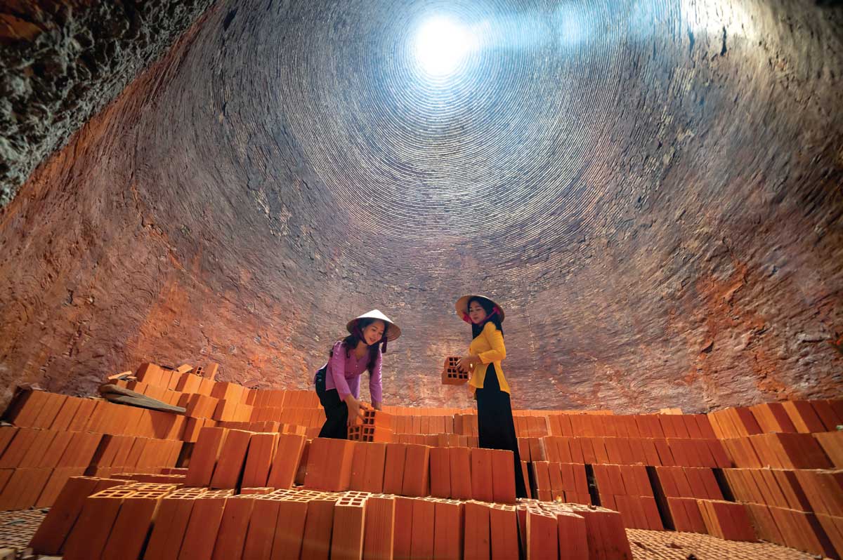
The disadvantage to brick refractory is that it is kept in place much like a roman arch: bricks are held in place by the pressure of the other bricks pushing against each other. When a problem is encountered, typically the failed brick needs to be replaced, but when one brick is relying on the bricks around it to hold it in place, often one cannot replace just one brick, and whole sections of the refractory must be replaced. Unlike castable refractory, the repair of a failure in brick refractory is much more involved.

Need and Function of Refractory in a RotaryKiln
Cement rotary kilns are kilns that conduct pyroprocessing. It is a machinery in the cement manufacturing plant that is used to heat materials to high temperatures in a continuous process. The kiln body is a cylinder vessel with a certain degree of tilt to the horizontal level. Raw materials are fed into the vessel from the upper end and moved to the lower end, being stirred and mixed relying on the inclination and rotation of the kiln. The kiln burner produces a lot of heat by burning fuel. This kind of heat is usually transferred to materials through flame radiation, hot gas convection, kiln brick conduction, etc., which causes the chemical reaction between raw materials and finally forms a clinker.

Rotary kilns can be divided into cement kilns, metallurgical and chemical rotary kilns, lime rotary kilns and so on. Cement rotary kilns are used for calcining cement clinkers in the cement plant, which can be divided into dry cement kilns and wet cement kilns. Metallurgical and chemical rotary kilns are mainly applied in the metallurgical industry. As for the lime rotary kiln, it is the main equipment for calcining active lime and light burned dolomite used in iron and steel plants, ferroalloy plants, calcium carbide plants, and magnesium metal plants.

The cement rotary kiln is mainly composed of a cylinder, supporting device, drive gear, refractory lining, catch-wheel device, kiln head sealing device, kiln tail sealing device, kiln hood, and other components. On the cylinder, there is a large gear ring fixed with a spring plate near the kiln tail; some pinions below are engaged with it, jointly forming the drive gear. In normal operation, the main drive motor will transfer power to this gear device through a reducer to run a rotary kiln. The raw material usually enters the rotary kiln from the upper end and moves slowly to another end along with the chamber as it rotates. In this process, raw materials will be heated by high temperature and then decompose and produce chemical reactions so that their state finally changes. Under normal conditions, the heat source of indirect fired rotary kilns is supplied from the kiln burner outside the kiln. This kind of way protects the integrity of raw materials, while the heat source of the direct-fired rotary kiln is inside the kiln. Besides, the rotation speed and temperature of the cylinder are tightly controlled and changed according to different desired processes and material applications. After the calcination is completed, the clinker will be pre-cooled in the chamber and then be sent into the cooler for further cooling.

With the continuous progress of the cement industry, rotary kilns, as the core cement equipment of the cement production line, is developing towards a large scale. Compared with the traditional rotary kiln, its technology is more complex, and the requirements for rotary kiln design and accessories are higher. The rotary kiln refractory lining is a layer of refractory material installed inside the kiln cylinder, which plays a protective role in many aspects, and is an important part of cement rotary kiln.

To protect the shell of the kiln from the high temperatures of the feed and combustion gases, a brick lining is used. Refractories play a critical role in both the rotary kiln lining, and the lining of the high-volume static equipment areas that comprise a modern pre-calciner kiln system.

Refractories require an insulating coating or lining further helping its function of preventing heat from escaping the kiln. Some of the key features that this coating material must have are:

  • High adhering potential to the lining and bricks
  • Mouldable to various shapes and sizes to fill in the gaps and holes of the brick lining
  • Acts as a protective layer against corrosion from flames and molten substances
  • Provides thermal spalling
  • Improves surface resistance to erosions and voids.

Layers of Refractories

Refractory is a customisable part of the rotary kiln and can be designed to suit the requirement of the desired clinker and subsequently, the end product of the process, cement. It can be tailored with multiple layers to meet the demands of a given application.

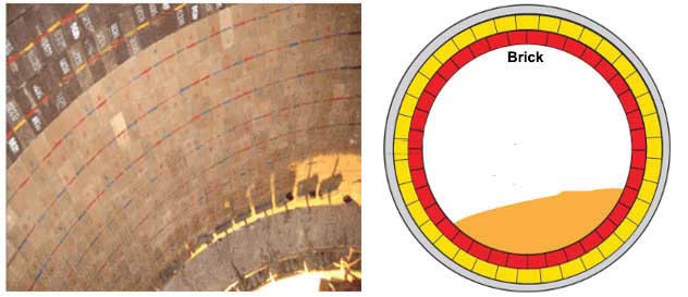
A refractory mostly has two layers, the working layer and the insulating layer and the combined thickness of the two ranges from 4.5 inches to 12 inches. They are made with materials that can withstand the high temperature process that takes place in the cement manufacturing process.

Working layer is designed with durable materials designed to withstand the heat within the rotary kiln as it comes directly in contact with the materials and raw mix being processed. It also goes through constant abrasion as it comes in contact with the materials.

An insulating layer is required beneath the working layer of the refractory to prevent the heat from slipping out to the shell of the kiln. This would be both dangerous as well as would lead to loss of efficiency and productivity of the process. It would also lead to damage of the kiln shell.

Typically, the working layer and the insulating layer are made of the same material (ie. brick or castable), with varying chemistries. The working layer tends to be a higher density, stronger material that is more conductive. The insulating layer does not need these qualities, and tends to be softer, lighter, and less conductive, therefore more insulating. These two layers often vary in thicknesses, determined by the needs of the rotary kiln and what material is being processed. In some cases, such as when temperatures are low, or when efficiency is not a concern, a single working layer may be all that is needed.

In contrast, when insulation is extremely critical, an optional third layer of ceramic fibre backing may be used. This thin, but very efficient layer is like fibreglass insulation found in a house, but it is much more compressed. The decision to employ this layer comes with some responsibility. Should a crack in the refractory occur and go unnoticed, it is possible for the high heat inside the rotary kiln to reach this backing and burn it up. This would create a gap between the refractory and the shell of the rotary kiln, which would cause disastrous problems. Due to this potential of increased risk, this third layer is not always appropriate.

Refractory Materials

A refractory is made of inert inorganic solid materials like oxides, carbides, nitrides, and borides of aluminium, silicon, alkaline earth metals, and transition metals. The key requirements of the materials from which a refractory is built are to be stable at high temperatures and to retain their original physical shape when they are exposed to corrosive solid, liquid or gaseous materials. Out of all these materials, very few qualify to be used in industrial scale, because of their instability under normal atmospheric conditions or because of the rare availability and high cost.

“Cement manufacturing is an energy intensive process. Burning alkaline raw materials (reactive) combined with smaller constituents of metals and abrasive raw materials at very high temperature is a major challenge. Therefore, a good refractory that can withstand high temperatures while retaining required strength and that is resistant to chemical properties of the alkaline raw materials is crucial. Besides, chemical attacks from sulphates or chlorine from the kiln feed, fuel or alternative fuels there are other factors that need to be factored in,” says Prabhat Singh Parihar, Vice President Technical Head, Mangrol Plant, JK Cement.

The source of the raw materials can be natural or synthetic. The raw materials used for refractory manufacturing are mainly naturally occurring minerals like bauxite, magnesite, clay etc., which are mined and processed before being used for refractory manufacturing. Some synthetic materials like mullite (3Al2O3.2SiO2), fused alumina (Al2O3), silicon carbide (SiC), spinel (MgO.Al2O3) etc., are also being used widely in refractories for the cement industry.

Operating Condition for Refractories

According to a report – Refractories Selection for Cement Industry, August 2020 published by IN Chakraborty, Ace Calderys Limited, Nagpur, refractory selection is the most important step for the maximisation of its performance.

Refractories play a critical role in both the rotary kiln lining, and the lining of the high-volume static equipment
areas that comprise a modern pre-calciner kiln system.

The major deciding factors for refractory selection are the working environment where the refractory would be used. The working environment, in general, is defined by the following parameters:

  • Operating temperature
  • Chemical condition
  • Chemical nature of solid or liquid, i.e., acidic, or basic, in contact with the refractory
  • Characteristic of the gaseous environment
  • Thermal shock
  • Mechanical stress
  • Abrasion

Refractory selection is the most important step for the maximisation of its performance. The major deciding factor for refractory selection is the working or operating environment where the refractory would be used. The working environment, in general, is defined by the following parameters:

Identification of critical parameters for a given working environment is vital for refractory life maximisation at optimal cost. Once the critical operating parameters are identified, the refractory should be so selected that it can withstand the operating condition for the stipulated lifespan. In the context of the refractory life in the cement rotary kiln, the lining design as well as the quality of refractory installation play a very critical role.

As a function of the cement manufacturing process, a raw meal i.e., a mix of limestone, quartz, clay and some lateritic material is fed in the kiln. This operating condition in this kiln is not severe except for in the burning zone where temperature can go up to 1450oC and the liquid content of the feed material falls in the range of 25 per cent to 27 per cent

By the time the raw mix attains a temperature of 900oC, the limestone present in the raw material is decomposed and quartz undergoes polymorphic transformation and cement constituents like C2S and C3A start forming. None of these have an adverse effect on the refractory. As the temperature rises to 1400oC, the liquid phase forms. At the maximum operating temperature, approximately 1450oC, the liquid phase concentration is about 25 per cent. On cooling down the C3S and C4AF precipitate out from the melt. As the clinker cools down, the reactivity of the mass reduces, i.e., the refractory is not chemically affected. However, the cold clinker becomes abrasive and may cause erosions on the refractory.

This operating condition of the kiln is of moderate severity from the chemical reactions point of view. The temperature in the non-burning zone part of the kiln system is not high enough for a chemical reaction between the aluminous refractory and the lime bearing raw material of the clinker.

This situation, however, becomes severe when alternative fuels are used. It is their alkali and chlorine concentrations that are significantly high compared to the conventional fuels. The melting points of these alkali compounds are lower than the maximum operating temperature of the kiln, hence, they evaporate in the kiln and travel along with the flue gas towards the kiln inlet areas whereas the rest escape in the kiln system by combining with the clinker. This alkali bearing gas then gets deposited on the incoming raw meal at the corresponding feeding point of these alkali compounds. The alkali enriched raw meal travels back to the kiln and the process repeats.

Refractory failure inside the rotary kiln is indicated when the kiln shell becomes red hot because the refractory lining
has either been entirely lost or has become too thin.

The chloride compounds have a lower melting point than the sulphates. They have the ability to travel further back in the kiln system, compared to sulphur bearing compounds. Owing to this cycling process, the kiln environment becomes richer in alkalis as compared to their concentration in the raw meals. Owing to the self-enrichment phenomenon, raw meal chemistry does not indicate the true chemical environment of the kiln.

Properties of Refractories

Refractories are characterised by their chemical and physical properties and are used to correlate its behaviour in actual high-temperature application.

Apparent Porosity: Refractories contain pores; some of the pores are open and connected and some are closed. The total volume of a refractory body is the sum of the volume of the matter, volume of the open pores and the volume of closed pores. The apparent porosity of a refractory is expressed in percentage and is defined as a percentage of the volume of open pores against the total volume.

It is a very important property and influences the mechanical strength, corrosion resistance, and thermal conductivity of a refractory. Porosity and bulk density of a refractory are inversely related. The lower the apparent porosity, the more will be the bulk density, mechanical strength, thermal conductivity, and corrosion resistance of the body. Besides total pore volume, the pore sizes are also very important to influence the corrosion resistance and thermal conductivity of the refractory. The smaller the pore sizes, the better is the corrosion resistance and the lower is the thermal conductivity.

Permeability: It is the measure of flow of gases through pores within the refractory body, and it indicates the extent of pore linkage. Permeability of refractories gives an indication on how well the Refractory will stand up to molten slag, a melt or to a gas penetration.

“The apparent porosity or open porosity (oPo) is the volume of the open pores, into which a liquid can penetrate, as a percentage of the total volume of the refractory. This property is important when the refractory is in contact with molten charge. A low apparent porosity prevents molten material from penetrating into the refractory, it makes a materialto- material bond and develops a good and stable coating on refractory / bricks, which enhances its life and its resistance to corrosion,” says Pradeep Kumar Chouhan, General Manager – Quality Control & Environment, Udaipur Cement Works Limited.

“The permeability of refractories is a governing factor in the deterioration of linings by liquids and gases. The permeability of any refractory material is defined as the volume of the gas or air, which passes through a cubic centimetre of material under a pressure of 10 mmWG per seconds” he adds.

Bulk Densities: It is the mass of the material per unit volume including pores. For the same kind of refractory, the bulk density can vary. The higher is the bulk density, the lesser will be the porosity and normally more will be the mechanical strength.

Specific Gravity: All different refractory minerals have different densities. They can be identified by their specific gravities. The specific gravity of a refractory can be determined by making powder of the sample of a specific size and using a specific gravity bottle and a balance.

Refractories are subjected to extreme temperatures and conditions. This is also a test of their mechanical properties. Some of the key mechanical properties of a refractory are:Cold Crushing StrengthModulus RuptureModulus of ElasticityFractureAbrasion Resistance

Factors Affecting the Maintenance of Refractories

Among kiln operators, refractory failure is considered the most critical upset in a kiln operation. Refractory failure inside the rotary kiln is indicated when the kiln shell becomes red hot because the refractory lining has either been entirely lost or has become so thin in an area that the kiln shell becomes overheated.

In most instances, however, damage can be avoided if the kiln is shut down for lining replacement as soon as the shell starts to show a large red spot.

Replacement of the kiln lining, especially in the burning zone, is unfortunately a frequent necessity, exerting a large strain on the operating budget and on production schedules.

Many plants have found that refractory life is often directly proportional to the number of kiln shutdowns that were experienced while the refractory was in the kiln. The more shutdowns and kilns stop, the shorter the life. The danger of damaging the refractory is directly related to the rate of cooling of the kiln, the danger being the greatest when cooling is too rapid.

When processing a highly abrasive material, a brick refractory is advisable.

The first step in preventing this situation is to eliminate shutdowns by operating the kiln more efficiently on a continuous basis. The second step is to make sure that cooling is slow and uniform when the kiln is shut down. Cooling time should be a minimum of 8 hours or longer. Placing a large guillotine damper to seal the kiln exit (back-end) helps to conserve heat inside the kiln and retards cooling during a shutdown. Another method of ensuring slow cooling of the refractory in the kiln is to shut the draft fan immediately when the fire is taken out of the kiln.

The primary air fan should be left running only for such a time as needed to protect the burner pipe from heat during the early period of kiln cooling.

As rapid cooling can cause damage to the refractory, so can rapidly heating it. Heating up the refractory quickly can cause thermal deterioration of the brick. Governed partly by the concept of thermal conductivity of the refractory, the kiln shell expansion takes place slower than the bricks. Because of this, the heating process should be for a minimum of 16 hours and should be gradually built up.

Another important factor to be considered for the longevity of the refractory life is to avoid overheating it. This can be ensured by constant monitoring of the kiln temperature and taking corrective action if the temperature rises beyond the threshold.

Having the refractory installed uniformly and in a shapely manner as per the kiln and end product requirement prevents its wear and tear when exposed to high temperature and erosive conditions. Kiln managers should also select the right type of refractories for each location of the kiln which is easier said than done.

Building the right refractory is a key process in the cement manufacturing process as this protective layer of the kiln withstands high temperature and handles the process of converting limestone to clinker and its cooling. Having the right shape, size and composition of refractory in the manufacturing unit increases the overall productivity and efficiency of the cement manufacturing process, thus, also increasing the profitability of the organisation at large. Paying keen attention to its installation and maintenance is important and must be done on a regular basis under expert guidance.

Concrete

Balancing Rapid Economic Growth and Climate Action

Published

on

By

Shares


Dr Yogendra Kanitkar, VP R&D, and Dr Shirish Kumar Sharma, Assistant Manager R&D, Pi Green Innovations, look at India’s cement industry as it stands at the crossroads of infrastructure expansion and urgent decarbonisation.

The cement industry plays an indispensable role in India’s infrastructure development and economic growth. As the world’s second-largest cement producer after China, India accounts for more than 8 per cent of global cement production, with an output of around 418 million tonnes in 2023–24. It contributes roughly 11 per cent to the input costs of the construction sector, sustains over one million direct jobs, and generates an estimated 20,000 additional downstream jobs for every million tonnes produced. This scale makes cement a critical backbone of the nation’s development. Yet, this vitality comes with a steep environmental price, as cement production contributes nearly 7 per cent of India’s total carbon dioxide (CO2) emissions.
On a global scale, the sector accounts for 8 per cent of anthropogenic CO2 emissions, a figure that underscores the urgency of balancing rapid growth with climate responsibility. A unique challenge lies in the dual nature of cement-related emissions: about 60 per cent stem from calcination of limestone in kilns, while the remaining 40 per cent arise from the combustion of fossil fuels to generate the extreme heat of 1,450°C required for clinker production (TERI 2023; GCCA).
This dilemma is compounded by India’s relatively low per capita consumption of cement at about 300kg per year, compared to the global average of 540kg. The data reveals substantial growth potential as India continues to urbanise and industrialise, yet this projected rise in consumption will inevitably add to greenhouse gas emissions unless urgent measures are taken. The sector is also uniquely constrained by being a high-volume, low-margin business with high capital intensity, leaving limited room to absorb additional costs for decarbonisation technologies.
India has nonetheless made notable progress in improving the carbon efficiency of its cement industry. Between 1996 and 2010, the sector reduced its emissions intensity from 1.12 tonnes of CO2 per ton of cement to 0.719 tonnes—making it one of the most energy-efficient globally. Today, Indian cement plants reach thermal efficiency levels of around 725 kcal/kg of clinker and electrical consumption near 75 kWh per tonne of cement, broadly in line with best global practice (World Cement 2025). However, absolute emissions continue to rise with increasing demand, with the sector emitting around 177 MtCO2 in 2023, about 6 per cent of India’s total fossil fuel and industrial emissions. Without decisive interventions, projections suggest that cement manufacturing emissions in India could rise by 250–500 per cent by mid-century, depending on demand growth (Statista; CEEW).
Recognising this threat, the Government of India has brought the sector under compliance obligations of the Carbon Credit Trading Scheme (CCTS). Cement is one of the designated obligated entities, tasked with meeting aggressive reduction targets over the next two financial years, effectively binding companies to measurable progress toward decarbonisation and creating compliance-driven demand for carbon reduction and trading credits (NITI 2025).
The industry has responded by deploying incremental decarbonisation measures focused on energy efficiency, alternative fuels, and material substitutions. Process optimisation using AI-driven controls and waste heat recovery systems has made many plants among the most efficient worldwide, typically reducing fuel use by 3–8 per cent and cutting emissions by up to 9 per cent. Trials are exploring kiln firing with greener fuels such as hydrogen and natural gas. Limited blends of hydrogen up to 20 per cent are technically feasible, though economics remain unfavourable at present.
Efforts to electrify kilns are gaining international attention. For instance, proprietary technologies have demonstrated the potential of electrified kilns that can reach 1,700°C using renewable electricity, a transformative technology still at the pilot stage. Meanwhile, given that cement manufacturing is also a highly power-intensive industry, several firms are shifting electric grinding operations to renewable energy.
Material substitution represents another key decarbonisation pathway. Blended cements using industrial by-products like fly ash and ground granulated blast furnace slag (GGBS) can significantly reduce the clinker factor, which currently constitutes about 65 per cent in India. GGBS can replace up to 85 per cent of clinker in specific cement grades, though its future availability may fall as steel plants decarbonise and reduce slag generation. Fly ash from coal-fired power stations remains widely used as a low-carbon substitute, but its supply too will shrink as India expands renewable power. Alternative fuels—ranging from biomass to solid waste—further allow reductions in fossil energy dependency, abating up to 24 per cent of emissions according to pilot projects (TERI; CEEW).
Beyond these, Carbon Capture, Utilisation, and Storage (CCUS) technologies are emerging as a critical lever for achieving deep emission cuts, particularly since process emissions are chemically unavoidable. Post-combustion amine scrubbing using solvents like monoethanolamine (MEA) remains the most mature option, with capture efficiencies between 90–99 per cent demonstrated at pilot scale. However, drawbacks include energy penalties that require 15–30 per cent of plant output for solvent regeneration, as well as costs for retrofitting and long-term corrosion management (Heidelberg Materials 2025). Oxyfuel combustion has been tested internationally, producing concentrated CO2-laden flue gas, though the high cost of pure oxygen production impedes deployment in India.
Calcium looping offers another promising pathway, where calcium oxide sorbents absorb CO2 and can be regenerated, but challenges of sorbent degradation and high calcination energy requirements remain barriers (DNV 2024). Experimental approaches like membrane separation and mineral carbonation are advancing in India, with startups piloting systems to mineralise flue gas streams at captive power plants. Besides point-source capture, innovations such as CO2 curing of concrete blocks already show promise, enhancing strength and reducing lifecycle emissions.
Despite progress, several systemic obstacles hinder the mass deployment of CCUS in India’s cement industry. Technology readiness remains a fundamental issue: apart from MEA-based capture, most technologies are not commercially mature in high-volume cement plants. Furthermore, CCUS is costly. Studies by CEEW estimate that achieving net-zero cement in India would require around US$ 334 billion in capital investments and US$ 3 billion annually in operating costs by 2050, potentially raising cement prices between 19–107 per cent. This is particularly problematic for an industry where companies frequently operate at capacity utilisations of only 65–70 per cent and remain locked in fierce price competition (SOIC; CEEW).
Building out transport and storage infrastructure compounds the difficulty, since many cement plants lie far from suitable geological CO2 storage sites. Moreover, retrofitting capture plants onto operational cement production lines adds technical integration struggles, as capture systems must function reliably under the high-particulate and high-temperature environment of cement kilns.
Overcoming these hurdles requires a multi-pronged approach rooted in policy, finance, and global cooperation. Policy support is vital to bridge the cost gap through instruments like production-linked incentives, preferential green cement procurement, tax credits, and carbon pricing mechanisms. Strategic planning to develop shared CO2 transport and storage infrastructure, ideally in industrial clusters, would significantly lower costs and risks. International coordination can also accelerate adoption.
The Global Cement and Concrete Association’s net-zero roadmap provides a collaborative template, while North–South technology transfer offers developing countries access to proven technologies. Financing mechanisms such as blended finance, green bonds tailored for cement decarbonisation and multilateral risk guarantees will reduce capital barriers.
An integrated value-chain approach will be critical. Coordinated development of industrial clusters allows multiple emitters—cement, steel, and chemicals—to share common CO2 infrastructure, enabling economies of scale and lowering unit capture costs. Public–private partnerships can further pool resources to build this ecosystem. Ultimately, decarbonisation is neither optional nor niche for Indian cement. It is an imperative driven by India’s growth trajectory, environmental sustainability commitments, and changing global markets where carbon intensity will define trade competitiveness.
With compliance obligations already mandated under CCTS, the cement industry must accelerate decarbonisation rapidly over the next two years to meet binding reduction targets. The challenge is to balance industrial development with ambitious climate goals, securing both economic resilience and ecological sustainability. The pathway forward depends on decisive governmental support, cross-sectoral innovation, global solidarity, and forward-looking corporate action. The industry’s future lies in reframing decarbonisation not as a burden but as an investment in competitiveness, climate alignment and social responsibility.

References

  • Infomerics, “Indian Cement Industry Outlook 2024,” Nov 2024.
  • TERI & GCCA India, “Decarbonisation Roadmap for the Indian Cement Industry,” 2023.
  • UN Press Release, GA/EF/3516, “Global Resource Efficiency and Cement.”
  • World Cement, “India in Focus: Energy Efficiency Gains,” 2025.
  • Statista, “CO2 Emissions from Cement Manufacturing 2023.”
  • Heidelberg Materials, Press Release, June 18, 2025.
  • CaptureMap, “Cement Carbon Capture Technologies,” 2024.
  • DNV, “Emerging Carbon Capture Techniques in Cement Plants,” 2024.
  • LEILAC Project, News Releases, 2024–25.
  • PMC (NCBI), “Membrane-Based CO2 Capture in Cement Plants,” 2024.
  • Nature, “Carbon Capture Utilization in Cement and Concrete,” 2024.
  • ACS Industrial Engineering & Chemistry Research, “CCUS Integration in Cement Plants,” 2024.
  • CEEW, “How Can India Decarbonise for a Net-Zero Cement Industry?” (2025).
  • SOIC, “India’s Cement Industry Growth Story,” 2025.
  • MDPI, “Processes: Challenges for CCUS Deployment in Cement,” 2024.
  • NITI Aayog, “CCUS in Indian Cement Sector: Policy Gaps & Way Forward,” 2025.

ABOUT THE AUTHOR:
Dr Yogendra Kanitkar, Vice President R&D, Pi Green Innovations, drives sustainable change through advanced CCUS technologies and its pioneering NetZero Machine, delivering real decarbonisation solutions for hard-to-abate sectors.

Dr Shirish Kumar Sharma, Assitant Manager R&D, Pi Green Innovations, specialises in carbon capture, clean energy, and sustainable technologies to advance impactful CO2 reduction solutions.

Continue Reading

Concrete

Carbon Capture Systems

Published

on

By

Shares


Nathan Ashcroft, Director, Strategic Growth, Business Development, and Low Carbon Solutions – Stantec, explores the challenges and strategic considerations for cement industry as it strides towards Net Zero goals.

The cement industry does not need a reminder that it is among the most carbon-intensive sectors in the world. Roughly 7–8 per cent of global carbon dioxide (CO2) emissions are tied to cement production. And unlike many other heavy industries, a large share of these emissions come not from fuel but from the process itself: the calcination of limestone. Efficiency gains, fuel switching, and renewable energy integration can reduce part of the footprint. But they cannot eliminate process emissions.
This is why carbon capture and storage (CCS) has become central to every serious discussion
about cement’s pathway to Net Zero. The industry already understands and accepts this challenge.
The debate is no longer whether CCS will be required—it is about how fast, affordable, and seamlessly it can be integrated into facilities that were never designed for it.

In many ways, CCS represents the ‘last mile’of cement decarbonisation. Once the sector achieves effective capture at scale, the most difficult part of its emissions profile will have been addressed. But getting there requires navigating a complex mix of technical, operational, financial and regulatory considerations.

A unique challenge for cement
Cement plants are built for durability and efficiency, not for future retrofits. Most were not designed with spare land for absorbers, ducting or compression units. Nor with the energy integration needs of capture systems in mind. Retrofitting CCS into these existing layouts presents a series of non-trivial challenges.
Reliability also weighs heavily in the discussion. Cement production runs continuously, and any disruption has significant economic consequences. A CCS retrofit typically requires tie-ins to stacks and gas flows that can only be completed during planned shutdowns. Even once operational, the capture system must demonstrate high availability. Otherwise, producers may face the dual cost of capture downtime and exposure to carbon taxes or penalties, depending on jurisdiction.
Despite these hurdles, cement may actually be better positioned than some other sectors. Flue gas from cement kilns typically has higher CO2 concentrations than gas-fired power plants, which improves capture efficiency. Plants also generate significant waste heat, which can be harnessed to offset the energy requirements of capture units. These advantages give the industry reason to be optimistic, provided integration strategies are carefully planned.

From acceptance to implementation
The cement sector has already acknowledged the inevitability of CCS. The next step is to turn acceptance into a roadmap for action. This involves a shift from general alignment around ‘the need’ toward project-level decisions about technology, layout, partnerships and financing.
The critical questions are no longer about chemistry or capture efficiency. They are about the following:

  • Space and footprint: Where can capture units be located? And how can ducting be routed in crowded plants?
  • Energy balance: How can capture loads be integrated without eroding plant efficiency?
  • Downtime and risk: How will retrofits be staged to avoid prolonged shutdowns?
  • Financing and incentives: How will capital-intensive projects be funded in a sector with
    tight margins?
  • Policy certainty: Will governments provide the clarity and support needed for long-term investment
  • Technology advancement: What are the latest developments?
  • All of these considerations are now shaping the global CCS conversation in cement.

Economics: The central barrier
No discussion of CCS in the cement industry is complete without addressing cost. Capture systems are capital-intensive, with absorbers, regenerators, compressors, and associated balance-of-plant representing a significant investment. Operational costs are dominated by energy consumption, which adds further pressure in competitive markets.
For many producers, the economics may seem prohibitive. But the financial landscape is changing rapidly. Carbon pricing is becoming more widespread and will surely only increase in the future. This makes ‘doing nothing’ an increasingly expensive option. Government incentives—ranging from investment tax credits in North America to direct funding in Europe—are accelerating project viability. Some producers are exploring CO2 utilisation, whether in building materials, synthetic fuels, or industrial applications, as a way to offset costs. This is an area we will see significantly more work in the future.
Perhaps most importantly, the cost of CCS itself is coming down. Advances in novel technologies, solvents, modular system design, and integration strategies are reducing both capital requirements
and operating expenditures. What was once prohibitively expensive is now moving into the range of strategic possibility.
The regulatory and social dimension
CCS is not just a technical or financial challenge. It is also a regulatory and social one. Permitting requirements for capture units, pipelines, and storage sites are complex and vary by jurisdiction. Long-term monitoring obligations also add additional layers of responsibility.
Public trust also matters. Communities near storage sites or pipelines must be confident in the safety and environmental integrity of the system. The cement industry has the advantage of being widely recognised as a provider of essential infrastructure. If producers take a proactive role in transparent engagement and communication, they can help build public acceptance for CCS
more broadly.

Why now is different
The cement industry has seen waves of technology enthusiasm before. Some have matured, while others have faded. What makes CCS different today? The convergence of three forces:
1. Policy pressure: Net Zero commitments and tightening regulations are making CCS less of an option and more of an imperative.
2. Technology maturity: First-generation projects in power and chemicals have provided valuable lessons, reducing risks for new entrants.
3. Cost trajectory: Capture units are becoming smaller, smarter, and more affordable, while infrastructure investment is beginning to scale.
This convergence means CCS is shifting from concept to execution. Globally, projects are moving from pilot to commercial scale, and cement is poised to be among the beneficiaries of this momentum.

A global perspective
Our teams at Stantec recently completed a global scan of CCS technologies, and the findings are encouraging. Across solvents, membranes, and
hybrid systems, innovation pipelines are robust. Modular systems with reduced footprints are
emerging, specifically designed to make retrofits more practical.
Equally important, CCS hubs—where multiple emitters can share transport and storage infrastructure—are beginning to take shape in key regions. These hubs reduce costs, de-risk storage, and provide cement producers with practical pathways to integration.

The path forward
The cement industry has already accepted the challenge of carbon capture. What remains is charting a clear path to implementation. The barriers—space, cost, downtime, policy—are real. But they are not insurmountable. With costs trending downward, technology footprints shrinking, and policy support expanding, CCS is no longer a distant aspiration.
For cement producers, the decision is increasingly about timing and positioning. Those who move early can potentially secure advantages in incentives, stakeholder confidence, and long-term competitiveness. Those who delay may face higher costs and tighter compliance pressures.
Ultimately, the message is clear: CCS is coming to cement. The question is not if but how soon. And once it is integrated, the industry’s biggest challenge—process emissions—will finally have a solution.

ABOUT THE AUTHOR:
Nathan Ashcroft, Director, Strategic Growth, Business Development, and Low Carbon Solutions – Stantec, holds expertise in project management, strategy, energy transition, and extensive international leadership experience.

Continue Reading

Concrete

The Green Revolution

Published

on

By

Shares


MM Rathi, Joint President – Power Management, Shree Cement, discusses the 3Cs – cut emissions, capture carbon and cement innovation – that are currently crucial for India’s cement sector to achieve Net Zero goals.

India’s cement industry is a backbone of growth which stand strong to lead the way towards net zero. From highways and housing to metros and mega cities, cement has powered India’s rise as the world’s second-largest producer with nearly 600 million tonnes annual capacity. Yet this progress comes with challenges: the sector contributes around 5 per cent of national greenhouse gas emissions, while also facing volatile fuel prices, raw material constraints, and rising demand from rapid urbanisation.
This dual role—driving development while battling emissions—makes cement central to India’s Net Zero journey. The industry cannot pause growth, nor can it ignore climate imperatives. As India pursues its net-zero 2070 pledge, cement must lead the way. The answer lies in the 3Cs Revolution—Cut Emissions, Cement Innovation, Capture Carbon. This framework turns challenges into opportunities, ensuring cement continues to build India’s future while aligning with global sustainability goals.

Cut: Reducing emissions, furnace by furnace
Cement production is both energy- and carbon-intensive, but India has steadily emerged as one of the most efficient producers worldwide. A big part of this progress comes from the widespread use of blended cements, which now account for more than 73 per cent of production. By lowering the clinker factor to around 0.65, the industry is able to avoid nearly seven million tonnes of CO2 emissions every year. Alongside this, producers are turning to alternative fuels and raw materials—ranging from biomass and municipal waste to refuse-derived fuels—to replace conventional fossil fuels in kilns.
Efficiency gains also extend to heat and power. With over 500 MW of waste heat recovery systems already installed, individual plants are now able to generate 15–18 MW of electricity directly from hot exhaust gases that would otherwise go to waste. On the renewable front, the sector is targeting about 10 per cent of its power needs from solar and wind by FY26, with a further 4–5 GW of capacity expected by 2030. To ensure that this renewable power is reliable, companies are signing round-the-clock supply contracts that integrate solar and wind with battery energy storage systems (BESS). Grid-scale batteries are also being explored to balance the variability of renewables and keep kiln operations running without interruption.
Even logistics is being reimagined, with a gradual shift away from diesel trucks toward railways, waterways, and CNG-powered fleets, reducing both emissions and supply chain congestion. Taken together, these measures are not only cutting emissions today but also laying the foundation for future breakthroughs such as green hydrogen-fueled kiln operations.

Cement: Innovations that bind
Innovation is transforming the way cement is produced and used, bringing efficiency, strength, and sustainability together. Modern high-efficiency plants now run kilns capable of producing up to 13,500 tonnes of clinker per day. With advanced coolers and pyro systems, they achieve energy use as low as 680 kilocalories per kilogram of heat and just 42 kilowatt-hours of power per tonne of clinker. By capturing waste heat, these plants are also able to generate 30–35 kilowatt-hours of electricity per tonne, bringing the net power requirement down to only 7–12 kilowatt-hours—a major step forward in energy efficiency.
Grinding technology has also taken a leap. Next-generation mills consume about 20 per cent less power while offering more flexible operations, allowing producers to fine-tune processes quickly and reduce energy costs. At the same time, the use of supplementary cementitious materials (SCMs) such as fly ash, slag and calcined clays is cutting clinker demand without compromising strength. New formulations like Limestone Calcined Clay Cement (LC3) go even further, reducing emissions by nearly 30 per cent while delivering stronger, more durable concrete.
Digitalisation is playing its part as well. Smart instrumentation, predictive maintenance, and automated monitoring systems are helping plants operate more smoothly, avoid costly breakdowns, and maintain consistent quality while saving energy. Together, these innovations not only reduce emissions but also enhance durability, efficiency, and cost-effectiveness, proving that sustainability and performance can go hand in hand.

Carbon: Building a better tomorrow
Even with major efficiency gains, most emissions from cement come from the chemical process of turning limestone into clinker—emissions that cannot be avoided without carbon capture. To address this, the industry is moving forward on several fronts. Carbon Capture, Utilisation and Storage (CCUS) pilots are underway, aiming to trap CO2 at the source and convert it into useful products such as construction materials and industrial chemicals.
At the same time, companies are embracing circular practices. Rainwater harvesting, wastewater recycling, and the use of alternative raw materials are becoming more common, especially as traditional sources like fly ash become scarcer. Policy and market signals are reinforcing this transition: efficiency mandates, green product labels and emerging carbon markets are pushing producers to accelerate the shift toward low-carbon cements.
Ultimately, large-scale carbon capture will be essential if the sector is to reach true net-zero
cement, turning today’s unavoidable emissions into tomorrow’s opportunities.

The Horizon: What’s next
By 2045, India’s cities are expected to welcome another 250 million residents, a wave of urbanisation that will push cement demand nearly 420 million tonnes by FY27 and keep rising in the decades ahead. The industry is already preparing for this future with a host of forward-looking measures. Trials of electrified kilns are underway to replace fossil fuel-based heating, while electric trucks are being deployed both in mining operations and logistics to reduce transport emissions. Inside the plants, AI-driven systems are optimising energy use and operations, and circular economy models are turning industrial by-products from other sectors into valuable raw materials for cement production. On the energy front, companies are moving toward 100 per cent renewable power, supported by advanced battery storage to ensure reliability around the clock.
This vision goes beyond incremental improvements. The 3Cs Revolution—Cut, Cement, Carbon is about building stronger, smarter, and more sustainable foundations for India’s growth. Once seen as a hard-to-abate emitter, the cement sector is now positioning itself as a cornerstone of India’s climate strategy. By cutting emissions, driving innovations and capturing carbon, it is laying the groundwork for a net-zero future.
India’s cement sector is already among the most energy-efficient in the world, proving that growth and responsibility can go hand in hand. By cutting emissions, embracing innovation, and advancing carbon capture, we are not just securing our net-zero future—we are positioning India as a global leader in sustainable cement.

ABOUT THE AUTHOR:
MM Rathi, Joint President – Power Management, Shree Cement, comes with extensive expertise in commissioning and managing over 1000 MW of thermal, solar, wind, and waste heat power plants.

Continue Reading

Trending News