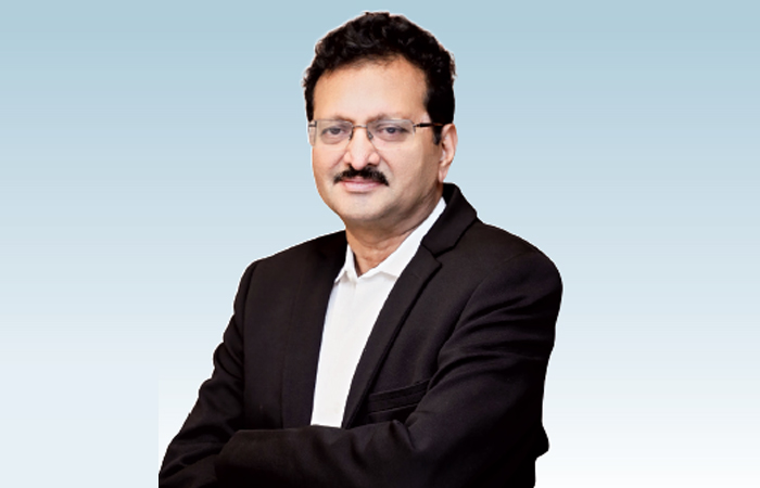
Connect with us

Product development

Coating on refractory brick lining

Published

on

Shares

Though refractory brick lining is installed with a purpose to protect the metallic shell of the kiln but often it is practised to have a good layer of coating on the brick lining. A majority of experts attribute it to the skills of a kiln operator.
A good protective coating on the refractory lining in the burning zone is always preferred to prolong the life of a refractory. Replacement of refractory bricks costs a large amount of money, loss in production while the kiln is down for lining replacement. In short replacement of refractory is an undesirable condition in any kiln.
Although refractories in the burning zone have to be replaced from time to time, a kiln operator has the capacity to increase or decrease the life of the lining by his ability to control the coating in the burning zone.Types of coatings
Coating is a mass of clinker or dust particles that sticks to the wall of the kiln, having changed from a liquid or semiliquid to a solidified state. The solidified particles stick to the surface of the coating (CS in Fig. 1), or the refractory surface (BS) when no coating exists, as long as the temperature of the surface of the coating is below the solidifying temperature of the particles. Coating continues to form until its surface reaches this solidifying temperature. When the kiln operates under such condition at equilibrium, the coating will maintain itself.
There is a temperature drop between the coating surface (CS) and the kiln shell (KS), the heat flowing in the direction indicated by the arrow (Fig. 1) (Heat always travels from a place or body of high temperature to a place of body of lower temperature). This heat transfer is governed to a great extent by the conductivity of the refractory and the coating. The better the conductivity of the refractory, the better the chance of coating formation, explained by the fact that the more heat that travels in the direction of the arrow. A kiln feed with a high liquid content at clinkering temperatures is more effective in coating formation than a feed low in liquid.
Kiln feeds with a high liquid phase (easy-burning mixes) have a high content of fluxes: the iron, alu?mina, magnesia, and alkalis. On the other hand, hard-burning mixes (low in iron, alumina, magnesia, and alkalis, and high in silica and lime) do not have a favourable influence on coating formation. Alkalis entrained in the gas stream promote the formation of coating and rings also because of their high fluxing characteristics.
Because the surface temperature is probably the most important factor in the formation of a coating, it is obvious that the flame itself has a significant effect on coating formation because the shape of the flame directly governs the surface temperature at any given point in the burning zone. A flame that is too short, snappy, and wide can erode the coating because of the great heat released over a short area with this kind of flame. A long flame is more favourable to coating formation in?the burning zone. It is observed that short flames are desirable for better control of the burning operation, but the flame should be shortened only to the extent that it will not harm the coating.
Once we ensure all favourable factors for good coating formation, it is then up to the kiln operator to control the coating during operation of the kiln. It is his responsibility to form and maintain a good solid coating in the burning zone.Operating conditions
Operating conditions are just as important for coating formation as all the other factors mentioned above. Assume that a kiln will be operated from one extreme of temperature to the other, that is, a cold, a normal, and a badly overheated kiln; that the same kiln-feed composition is burned in all three examples; that the solidifying temperature is around 1,3000 C; and that 24 per cent liquid is formed at the point of investigation, under ideal operating condition.
First, consider the cold kiln (Fig. 2). In this case almost no coating is formed. The coating surface temperature as well as the feed temperature is too low to produce the necessary amount of liquid matter that would promote coating formation. The condition in this example is commonly referred to by kiln operators as the kiln being in a ‘hole.’ This example also supports the widely known fact that no new coating can be formed while the kiln is cold.
In the normal kiln (Fig. 2), enough liquid (24 per cent) is present to form a coating. Temperature of the coating when it emerges from the feed bed, as well as when in contact with the feed, is below the solidifying temperature of the feed particles. The particles will adhere to the wall and solidify, and will continue to do so as long as the surface temperature of the coating remains below the solidifying temperature of 2,4000 F (1,3150 C). Whenever the wall reaches this temperature no new coating will form. The coating is in equilibrium.
In the hot kiln (Fig. 2), because of the extremely high temperatures of the feed and the coating, too much liquid is formed. As all temperatures are above the solidifying temperature, the coating transforms from a solid back to a liquid again. In such a condition, coating will come off, and the feed because of its high liquid content will ‘ball up.’ Needless to say, this condition is extremely harmful to the kiln and to the refractory.
Most basic refractories, are not able to withstand prolonged exposure to the high flame temperatures without this protective coating. As was mentioned in the previous chapter, the burning zone is divided into three subzones namely the upper-transition 1 the sintering, and the lower-transition zones. Because of the lower liquid content in the feed and because of the frequent temperature changes, the upper- and lower-transition zones are areas where formation and maintenance of coating is the most unstable.
Shifting burning zone locations produce a similar shift in the location where coating is formed; thus, unstable coating conditions are most frequently observed in the upper and lower end of the burning zone. This is clearly supported by the fact that most rotary kilns experience the most frequent refractory failures in these two critical areas. It should be noted that since the upper and lower burning zones are also within the vicinity of the first and second tires, brick failures are not only the result of variations in burning-zone conditions but, are also often the direct result of excessive tire clearance and shell ovality. Both the frequent falling out of coatings in these areas and the formation of too much coating can lead to troublesome ring formations.
Ring formations in the lower-transition zone (i.e., at the kiln discharge) are referred to as nose rings. Others refer to these as ash rings when the kiln is coal fired. Ring formations in the upper-transition zone are referred to as clinker rings. These ring formations can in many instances be so severe that they force operators to shut down the kiln and shoot these rings out with an industrial gun.
The possible causes are many and no one single factor has yet been found that would be the main cause for all the rings formed. What seems to be true for one particular kiln might be completely wrong for another kiln. On many coal-fired kilns, operators have found a relation?ship between the fusion temperature of the coal ash and the frequency of ring formation. There appears to be more ring formation when the fusion temperature is low, i.e., when the ash contains larger amounts of fluxing iron and alumina and less silica. However, this could not be the only cause for such ring formations because natural gas- and oil-fired kilns, which have no ash deposits in the burning zone, can have just as many ring problems as the coal-fired kilns.
Hence, solutions for the elimination of rings in the burning zone are predominantly found by a process of elimination. First, all probable causes are listed and then each suspected cause is eliminated or changed until hopefully an answer is found.
It is of interest that half of the causes of ring formation can be somehow controlled by the kiln operator and action taken to stabilise the flame and the kiln operation that might be beneficial in lessening the frequency of ring formation.Ring formation
Less frequent but nevertheless equally troublesome are the so-called feed rings that form in the calcining zone of the rotary kiln. It has been found that the majority of these rings and heavy coatings in kilns are associated with one of the following factors:

  • Internal cycle of the volatile constituents from the kiln feed and fuel (alkalis, sulphur, chlorides).
  • Kiln-feed fineness.
  • Irregular and insufficient control (frequent fluctuations) of the feed? end temperature and kiln draft.
  • Excessive dust generation within the rotary kiln proper.

Analysis of the materials from these rings or excessive coating builds invariably showed high contents of calcium sulphates, potassium chloride and/or alkali sulphur. Efforts to alter the internal and external cycle of volatile components in the gas or feed stream have in many instance resulted in less frequent ring formations. Causes for ring formation

  • Coal fineness too coarse
  • Low fusion temperature of coal ash
  • Kiln feed high on liquid content (silica, A/F ratios and or lime saturation factor low)
  • Incomplete calcination of the feed as it enters the burning zone
  • Frequent changes in chemical composition and fineness of kiln feed
  • Excessive dust generation in the cooler and burning zone
  • Kiln speed too slow and feed loading too high
  • Variations of flame temperature and length during normal operation
  • Changes in secondary air temperatures
  • Burning zone temperature and location varies too frequently and by too large a range
  • Increased volatility of, and frequent changes in, alkali and sulphur contents in the fuel and feed

Continue Reading
Click to comment

Leave a Reply

Your email address will not be published. Required fields are marked *

Economy & Market

Impactful Branding

Published

on

By

Shares

Advertising or branding is never about driving sales. It’s about creating brand awareness and recall. It’s about conveying the core values of your brand to your consumers. In this context, why is branding important for cement companies? As far as the customers are concerned cement is simply cement. It is precisely for this reason that branding, marketing and advertising of cement becomes crucial. Since the customer is unable to differentiate between the shades of grey, the onus of creating this awareness is carried by the brands. That explains the heavy marketing budgets, celebrity-centric commercials, emotion-invoking taglines and campaigns enunciating the many benefits of their offerings.
Marketing strategies of cement companies have undergone gradual transformation owing to the change in consumer behaviour. While TV commercials are high on humour and emotions to establish a fast connect with the customer, social media campaigns are focussed more on capturing the consumer’s attention in an over-crowded virtual world. Branding for cement companies has become a holistic growth strategy with quantifiable results. This has made brands opt for a mix package of traditional and new-age tools, such as social media. However, the hero of every marketing communication is the message, which encapsulates the unique selling points of the product. That after all is crux of the matter here.
While cement companies are effectively using marketing tools to reach out to the consumers, they need to strengthen the four Cs of the branding process – Consumer, Cost, Communication and Convenience. Putting up the right message, at the right time and at the right place for the right kind of customer demographic is of utmost importance in the long run. It is precisely for this reason that regional players are likely to have an upper hand as they rely on local language and cultural references to drive home the point. But modern marketing and branding domain is exponentially growing and it would be an interesting exercise to tabulate and analyse its impact on branding for cement.

Continue Reading

Concrete

Indian cement industry is well known for its energy and natural resource efficiency

Published

on

By

Shares

Dr Hitesh Sukhwal, Deputy General Manager – Environment, Udaipur Cement Works Limited (UCWL) takes us through the multifaceted efforts that the company has undertaken to keep emissions in check with the use of alternative sources of energy and carbon capture technology.

Tell us about the policies of your organisation for the betterment of the environment.
Caring for people is one of the core values of our JK Lakshmi Cement Limited. We strongly believe that we all together can make a difference. In all our units, we have taken measures to reduce carbon footprint, emissions and minimise the use of natural resources. Climate change and sustainable development are major global concerns. As a responsible corporate, we are committed with and doing consistent effort small or big to preserve and enrich the environment in and around our area of operations.
As far as environmental policies are concerned, we are committed to comply with all applicable laws, standards and regulations of regulatory bodies pertaining to the environment. We are consistently making efforts to integrate the environmental concerns into the mainstream of the operations. We are giving thrust upon natural resource conservation like limestone, gypsum, water and energy. We are utilising different kinds of alternative fuels and raw materials. Awareness among the employees and local people on environmental concerns is an integral part of our company. We are adopting best environmental practices aligned with sustainable development goals.
Udaipur Cement Works Limited is a subsidiary of the JK Lakshmi Cement Limited. Since its inception, the company is committed towards boosting sustainability through adopting the latest art of technology designs, resource efficient equipment and various in-house innovations. We are giving thrust upon renewable and clean energy sources for our cement manufacturing. Solar Power and Waste Heat Recovery based power are our key ingredients for total power mix.

What impact does cement production have on the environment? Elaborate the major areas affected.
The major environmental concern areas during cement production are air emissions through point and nonpoint sources due to plant operation and emissions from mining operation, from material transport, carbon emissions through process, transit, noise pollution, vibration during mining, natural resource depletion, loss of biodiversity and change in landscape.
India is the second largest cement producer in the world. The Indian cement industry is well known for its energy and natural resource efficiency worldwide. The Indian cement industry is a frontrunner for implementing significant technology measures to ensure a greener future.
The cement industry is an energy intensive and significant contributor to climate change. Cement production contributes greenhouse gases directly and indirectly into the atmosphere through calcination and use of fossil fuels in an energy form. The industry believes in a circular economy by utilising alternative fuels for making cement. Cement companies are focusing on major areas of energy efficiency by adoption of technology measures, clinker substitution by alternative raw material for cement making, alternative fuels and green and clean energy resources. These all efforts are being done towards environment protection and sustainable future.
Nowadays, almost all cement units have a dry manufacturing process for cement production, only a few exceptions where wet manufacturing processes are in operation. In the dry manufacturing process, water is used only for the purpose of machinery cooling, which is recirculated in a closed loop, thus, no polluted water is generated during the dry manufacturing process.
We should also accept the fact that modern life is impossible without cement. However, through state-of-the-art technology and innovations, it is possible to mitigate all kinds of pollution without harm to the environment and human beings.

Tell us about the impact blended cement creates on the environment and emission rate.
Our country started cement production in 1914. However, it was introduced in the year 1904 at a small scale, earlier. Initially, the manufacturing of cement was only for Ordinary Portland Cement (OPC). In the 1980s, the production of blended cement was introduced by replacing fly ash and blast furnace slag. The production of blended cement increased in the growth period and crossed the 50 per cent in the year 2004.
The manufacturing of blended cement results in substantial savings in the thermal and electrical energy consumption as well as saving of natural resources. The overall consumption of raw materials, fossil fuel such as coal, efficient burning and state-of-the-art technology in cement plants have resulted in the gradual reduction of emission of carbon dioxide (CO2). Later, the production of blended cement was increased in manifolds.
If we think about the growth of blended cement in the past few decades, we can understand how much quantity of , (fly ash and slag) consumed and saved natural resources like limestone and fossil fuel, which were anyhow disposed of and harmed the environment. This is the reason it is called green cement. Reduction in the clinker to cement ratio has the second highest emission reduction potential i.e., 37 per cent. The low carbon roadmap for cement industries can be achieved from blended cement. Portland Pozzolana Cement (PPC), Portland Slag Cement (PSC) and Composite Cement are already approved by the National Agency BIS.
As far as kilogram CO2 per ton of cement emission concerns, Portland Slag Cement (PSC) has a larger potential, other than PPC, Composite Cement etc. for carbon emission reduction. BIS approved 60 per cent slag and 35 per cent clinker in composition of PSC. Thus, clinker per centage is quite less in PSC composition compared to other blended cement. The manufacturing of blended cement directly reduces thermal and process emissions, which contribute high in overall emissions from the cement industry, and this cannot be addressed through adoption of energy efficiency measures.
In the coming times, the cement industry must relook for other blended cement options to achieve a low carbon emissions road map. In near future, availability of fly ash and slag in terms of quality and quantity will be reduced due to various government schemes for low carbon initiatives viz. enhance renewable energy sources, waste to energy plants etc.
Further, it is required to increase awareness among consumers, like individual home builders or large infrastructure projects, to adopt greener alternatives viz. PPC and PSC for more sustainable
resource utilisation.

What are the decarbonising efforts taken by your organisation?
India is the world’s second largest cement producer. Rapid growth of big infrastructure, low-cost housing (Pradhan Mantri Awas Yojna), smart cities project and urbanisation will create cement demand in future. Being an energy intensive industry, we are also focusing upon alternative and renewable energy sources for long-term sustainable business growth for cement production.
Presently, our focus is to improve efficiency of zero carbon electricity generation technology such as waste heat recovery power through process optimisation and by adopting technological innovations in WHR power systems. We are also increasing our capacity for WHR based power and solar power in the near future. Right now, we are sourcing about 50 per cent of our power requirement from clean and renewable energy sources i.e., zero carbon electricity generation technology. Usage of alternative fuel during co-processing in the cement manufacturing process is a viable and sustainable option. In our unit, we are utilising alternative raw material and fuel for reducing carbon emissions. We are also looking forward to green logistics for our product transport in nearby areas.
By reducing clinker – cement ratio, increasing production of PPC and PSC cement, utilisation of alternative raw materials like synthetic gypsum/chemical gypsum, Jarosite generated from other process industries, we can reduce carbon emissions from cement manufacturing process. Further, we are looking forward to generating onsite fossil free electricity generation facilities by increasing the capacity of WHR based power and ground mounted solar energy plants.
We can say energy is the prime requirement of the cement industry and renewable energy is one of the major sources, which provides an opportunity to make a clean, safe and infinite source of power which is affordable for the cement industry.

What are the current programmes run by your organisation for re-building the environment and reducing pollution?
We are working in different ways for environmental aspects. As I said, we strongly believe that we all together can make a difference. We focus on every environmental aspect directly / indirectly related to our operation and surroundings.
If we talk about air pollution in operation, every section of the operational unit is well equipped with state-of-the-art technology-based air pollution control equipment (BagHouse and ESP) to mitigate the dust pollution beyond the compliance standard. We use high class standard PTFE glass fibre filter bags in our bag houses. UCWL has installed the DeNOx system (SNCR) for abatement of NOx pollution within norms. The company has installed a 6 MW capacity Waste Heat Recovery based power plant that utilises waste heat of kiln i.e., green and clean energy source. Also, installed a 14.6 MW capacity solar power system in the form of a renewable energy source.
All material transfer points are equipped with a dust extraction system. Material is stored under a covered shed to avoid secondary fugitive dust emission sources. Finished product is stored in silos. Water spraying system are mounted with material handling point. Road vacuum sweeping machine deployed for housekeeping of paved area.
In mining, have deployed wet drill machine for drilling bore holes. Controlled blasting is carried out with optimum charge using Air Decking Technique with wooden spacers and non-electric detonator (NONEL) for control of noise, fly rock, vibration, and dust emission. No secondary blasting is being done. The boulders are broken by hydraulic rock breaker. Moreover, instead of road transport, we installed Overland Belt Conveying system for crushed limestone transport from mine lease area to cement plant. Thus omit an insignificant amount of greenhouse gas emissions due to material transport, which is otherwise emitted from combustion of fossil fuel in the transport system. All point emission sources (stacks) are well equipped with online continuous emission monitoring system (OCEMS) for measuring parameters like PM, SO2 and NOx for 24×7. OCEMS data are interfaced with SPCB and CPCB servers.
The company has done considerable work upon water conservation and certified at 2.76 times water positive. We installed a digital water flow metre for each abstraction point and digital ground water level recorder for measuring ground water level 24×7. All digital metres and level recorders are monitored by an in-house designed IoT based dashboard. Through this live dashboard, we can assess the impact of rainwater harvesting (RWH) and ground water monitoring.
All points of domestic sewage are well connected with Sewage Treatment Plant (STP) and treated water is being utilised in industrial cooling purposes, green belt development and in dust suppression. Effluent Treatment Plant (ETP) installed for mine’s workshop. Treated water is reused in washing activity. The unit maintains Zero Liquid Discharge (ZLD).
Our unit has done extensive plantations of native and pollution tolerant species in industrial premises and mine lease areas. Moreover, we are not confined to our industrial boundary for plantation. We organised seedling distribution camps in our surrounding areas. We involve our stakeholders, too, for our plantation drive. UCWL has also extended its services under Corporate Social Responsibility for betterment of the environment in its surrounding. We conduct awareness programs for employees and stakeholders. We have banned Single Use Plastic (SUP) in our premises. In our industrial township, we have implemented a solid waste management system for our all households, guest house and bachelor hostel. A complete process of segregated waste (dry and wet) door to door collection systems is well established.

Tell us about the efforts taken by your organisation to better the environment in and around the manufacturing unit.
UCWL has invested capital in various environmental management and protection projects like installed DeNOx (SNCR) system, strengthening green belt development in and out of industrial premises, installed high class pollution control equipment, ground-mounted solar power plant etc.
The company has taken up various energy conservation projects like, installed VFD to reduce power consumption, improve efficiency of WHR power generation by installing additional economiser tubes and AI-based process optimisation systems. Further, we are going to increase WHR power generation capacity under our upcoming expansion project. UCWL promotes rainwater harvesting for augmentation of the ground water resource. Various scientifically based WHR structures are installed in plant premises and mine lease areas. About 80 per cent of present water requirement is being fulfilled by harvested rainwater sourced from Mine’s Pit. We are also looking forward towards green transport (CNG/LNG based), which will drastically reduce carbon footprint.
We are proud to say that JK Lakshmi Cement Limited has a strong leadership and vision for developing an eco-conscious and sustainable role model of our cement business. The company was a pioneer among cement industries of India, which had installed the DeNOx (SNCR) system in its cement plant.

Continue Reading

Concrete

NTPC selects Carbon Clean and Green Power for carbon capture facility

Published

on

By

Shares

Carbon Clean and Green Power International Pvt. Ltd has been chosen by NTPC Energy Technology Research Alliance (NETRA) to establish the carbon capture facility at NTPC Vindhyachal. This facility, which will use a modified tertiary amine to absorb CO2 from the power plant’s flue gas, is intended to capture 20 tonnes of CO2) per day. A catalytic hydrogenation method will eventually be used to mix the CO2 with hydrogen to create 10 tonnes of methanol each day. For NTPC, capturing CO2 from coal-fired power plant flue gas and turning it into methanol is a key area that has the potential to open up new business prospects and revenue streams.

Continue Reading

Trending News

SUBSCRIBE TO THE NEWSLETTER


Don't miss out on valuable insights and opportunities to connect with like minded professionals.


    This will close in 0 seconds