
Concrete
Larger Gear Drives for Larger Vertical Roller Mills
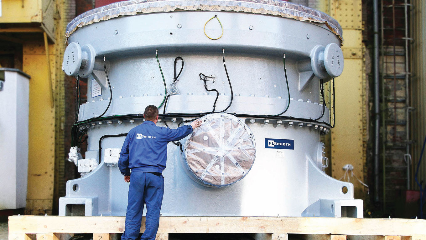
The global trend towards single-mill cement plants is unquestionable. With civil construction cost savings, higher throughput and lowered maintenance costs, the use of single large VRMs for cement and raw grinding is the optimal choice. The sheer size requires powerful, large-scale drive gear systems.
As operators look to increase equipment capacity, the key is to ensure long-term reliability that guarantees continuous kiln operation. There are several challenges. Whereas machine design is often the limiting factor for large ball mills and roller presses, it is the drive systems that require focus in vertical roller mills (VRMs). Placing silos before and after the kiln can reduce short interruptions in the milling processes, but long standstills caused by unexpected mechanical failures are difficult to avoid.
Reliability of VRMs depends on the drive system, the grinding system and the operational behaviour of the mill. To help lower initial cost investments aimed at preventing downtime, particular attention must be devoted to the drive system and critical grinding components, such as roller and table.
The rollers and the grinding table are exposed to high abrasive wear depending on the feed material properties, the product fineness, and the combination of rollers and table materials. At regular intervals, therefore, the table and roller wear liners must be exchanged or repaired by surface-layer welding.
Without the natural redundancy of an approach with two mills in parallel, flexibility is key. The OK™ mill has individual roller arrangements with swing-out mechanisms to facilitate maintenance or replacement of the rollers. In the case of mechanical failure, the mill can easily operate with fewer rollers. The only requirement is that the remaining rollers are uniformly distributed around the table circumference and that they are all the same size. Production can then continue, albeit at a reduced rate, to minimise operational disruption.
Impressively, the OK mill can achieve 60 to 70 per cent of nominal output with half of its rollers out of service.
“The design power of such large VRMs depends on the grindability of material. Raw mill applications require up to approximately 9,000kW, with slag and cement grinding needing up to 14,000kW. Regardless of the type, these VRMs’ drive systems need to deliver reliable torque transmission.”
Drive Systems
Conventional drive systems typically consist of a switch-gear to connect the drive motor to the electrical grid. The transformer converts the grid voltage to the motor design voltage and protects the equipment from voltage peaks. A rotor starting device and a highly flexible coupling connects the motor and gearbox.
Yet there are limits to such a system. The bevel stage in the gearbox, primarily used to redirect the rotating movement from the horizontal motor shaft into the vertical direction of the grinding table, limits power capability. For design power of up to approximately 9,000kW, this can be overcome by increasing the gear ratio in the following planetary stage, which keeps the bevel stage size within feasible dimensions. However, this does not fulfil mill requirements and a further increase in drive power requires larger dimensions, especially the diameter of the bevel wheels. This decreases the overall reliability of the drive system. Conventional gear units cannot operate VRMs with higher design power. The drive system for these applications is based on two main principles: partition of power to several drive units and elimination of the weakest element in the drive train.
Partitioning Drive Power
By separating the drive power, large VRMs can provide the required torque with multiple motors. The motors are designed either as individual drive assemblies containing their own motors, couplings and gearboxes or as small vertical motors, integrated partially into the gear casing and connected to a central toothed wheel inside the gearbox.
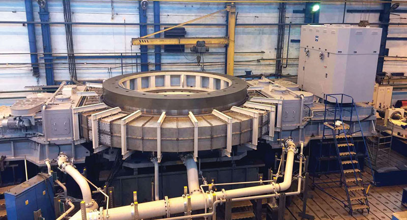
As a result, power distribution bevel stages are considerably smaller or, in vertical motors, completely eliminated. The drive systems are built so that they can operate with fewer motors in the case of malfunction or maintenance. This means that operation at a reduced production rate can still occur, minimising production losses during scheduled maintenance. This has the effect, however, of increasing complexity of the power distribution between the main switchgear and the motors and also increasing maintenance effort.
In addition to the main switch gear, each motor needs a separate circuit breaker and a motor control cabinet to allow operation with a reduced number of motors. In order to provide uniform torque to the common central wheels, the load and speed of each motor is synchronised by either a variable frequency converter or a highly flexible or fluid coupling. During start-up, when the mill is running at full speed with fewer motors, the timing of the connecting additional motors is essential to prevent torque peaks.
Elimination of Weakest Element
The integrated drive system in the VRM replaces the bevel stage with one vertical motor built into the gear casing. While this does not affect the power distribution, compared with the conventional system, the overall dimensions of the motor must be adapted to the available space for a bevel stage in a conventional gearbox. Otherwise, costly design changes of the mill support and foundation are required.
“The challenge with the integrated system is developing an electrical motor with the highest possible power density.”
A design study comparing different motor types showed that meeting space requirements is only possible with a synchronous motor with permanent magnet excitation and a single coil stator. To operate such type motors, variable frequency converters are necessary. Integration also makes special cooling necessary because air-cooled motors do not reach the required power density.
For example, the motor in FLSmidth MAAG® Gear’s CEM Drive includes special cooling tubes in the stator arrangement. This provides optimal flow of the cooling media and enables the use of gear lubrication oil in the motor cooling circuit.
Smart Design
Despite the challenges associated with large VRMs, there are important benefits to having an integrated drive system embedded in the design. Power distribution, such as that in a partial-load system, is not required and the number of rotating parts is kept to a minimum. The variable frequency converter allows the operator to adjust the mill table speed without time delay and to influence the grinding process individually when grinding different products in the same mill or as feed quality changes over time.
Large VRMs can help to meet the demands of a single-mill cement line by addressing the typical challenges of grinding systems. In doing so, FLSmidth’s OK mill can provide a solution for most single-mill cement lines wanting to increase their throughput.


Concrete
World Cement Association Annual Conference 2026 in Bangkok
Global leaders to focus on decarbonisation and digitisation

Concrete
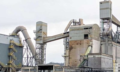
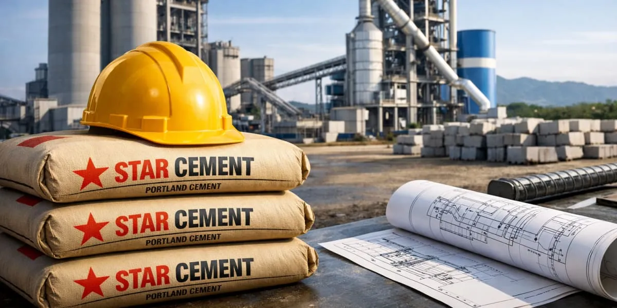
Assam Chief Minister Opens Star Cement Plant In Cachar
New plant aims to boost local industry and supply chains
Concrete
Adani Cement, NAREDCO Form Strategic Alliance
Partnership to advance skills and sustainable construction


World Cement Association Annual Conference 2026 in Bangkok

Assam Chief Minister Opens Star Cement Plant In Cachar

Adani Cement, NAREDCO Form Strategic Alliance

Walplast’s GypEx Range Secures GreenPro Certification

Smart Pumping for Rock Blasting
World Cement Association Annual Conference 2026 in Bangkok
Assam Chief Minister Opens Star Cement Plant In Cachar
Adani Cement, NAREDCO Form Strategic Alliance
Walplast’s GypEx Range Secures GreenPro Certification
Smart Pumping for Rock Blasting
-

 Economy & Market4 weeks ago
Budget 2026–27 infra thrust and CCUS outlay to lift cement sector outlook
-
 Economy & Market4 weeks ago
FORNNAX Appoints Dieter Jerschl as Sales Partner for Central Europe
-

 Concrete1 month ago
Steel: Shielded or Strengthened?
-

 Concrete2 weeks ago
Refractory demands in our kiln have changed