Connect with us

Concrete

New Concepts in Material Handling

Published

on

Shares

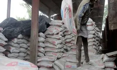
The cement industry can adopt newer material handling concepts with the help of a few innovations. Jai Gupta explores the new material handling ideas available and how these can be implemented.

The Indian cement industry has witnessed rapid growth in the past two decades. The overall production capacity of several sectors has doubled or even quadrupled over this period. Such rapid growth has posed several challenges for the industry, some of which are:

  • The conventional?easy to access? locations are no more available. New projects are forced to go for difficult-to-access locations from where material movements are difficult.
  • Land is gradually becoming a scarce resource. The industry is facing difficulties in land availability/ acquisition, and is hence being forced to go away from the markets or is being forced to manage in a limited area.
  • Unit sizes are becoming larger to harness economies of scale. Such enlargement in size is forcing the industry to market its products in larger areas.
  • With specific reference to the cement industry, growing demands and need of fly ash-based PPC production has forced many industry players to set up grinding units close to thermal power plants for fly ash consumption. As these thermal power plants are generally located closer to densely populated areas, space is always a constraint and hence they cannot develop good infrastructure for rail/road movement of material.

All the issues enumerated above are putting more and more pressure on the logistics of material movement. As material transportation is a sizeable portion of the total cost of production, any gains or reduction in cost of material movement could help the industry greatly.
Due to the needs of high capacity material movement at fast pace and inadequacy of road networks in remote areas, the industry?s reliance on rail transportation has substantially increased. Some good ideas have been implemented, relating to material movement through rail routes. These concepts have been successfully employed by Holtec in cement as well as other industries, and could help the industry in optimising expenses on material handling.

New Concepts in Material Handling
i.In-motion loading of material in railway rakes
ii.Movable wagon loader feeding stationary rakes
iii.Use of bottom discharge wagons for transport and its easy and fast unloading iv.Use of wagon shifters to substantially reduce the area required for the installation of a wagon tippler.

In-Motion Loading of Material in Railway Rakes
For majority of the industries requiring bulk material transportation, loading is usually done through either multiple overland hoppers constructed on top of the railway tracks, or manually through pay loaders. The usual time taken for one complete rake varies from three-six hours depending upon the arrangement or equipment employed. More number of hoppers or pay loaders can reduce the time taken; however, they add to certain other issues, such as:

  • Heavy to very heavy civil construction
  • More number of operators
  • Dust nuisance, spillages, material wastage and degradation etc.
  • With a rapid loading system, the entire rake can be loaded in about 60-80 minutes, from a single discharge point.

What is Rapid Loading?
In rapid loading of material, material is loaded on a rake, while the railway rake is in motion. One silo (of about one full rake capacity) is constructed on top of the rail track. Below the hopper, another small hopper is provided on load cells, which can accommodate about one wagonload of material. The above two hoppers are connected through hydraulic gates and a large chute, so that within seconds, material gets transferred from the main hopper to the pre-weigh hopper (mounted on the load cell).
Before a rake arrives, the silo is filled, so that fast material loading on the rake does not get disturbed. In the beginning, the load cell hopper is filled with pre-weighed material. As soon as the wagon comes in position, the loading starts and by the time it crosses, the complete wagon is loaded. During the period of wagon change, the pre-weigh hopper again receives the material from the main hopper, so that by the time another wagon comes into position, it is ready with the material. During this entire operation, the railway rake moves at the speed of about 0.6 to 0.7 km/hr. That means a full railway rake of about 650 m length is likely to get loaded in about one hour.
The majority of the collieries in India have been using the rapid loading system for coal rake loading.
Adopting a similar concept, Holtec designed a rapid loading system for lignite. As the system was designed for lignite, it was substantially different from the usual rapid loading system. However, it has been performing very successfully for the last 10-12 years. At this location, a rake of about 40 wagons is being loaded in about 45 minutes. Although the system is located close to a densely populated area, owners do not face any difficulties in operation as the process generates negligible dust. The material filling and closing is done through hydraulic gates, and wagon positioning is sensed through the proximity switches. A little bit of maintenance and care in operation is enough to keep the system spillage free.
At this location, there were several constraints such as poor soil bearing capacity, low water table, limited execution period, etc. Hence, while designing the system, three small silos were constructed to store one rake load of material, rather than a single hopper. A single hydraulic system was considered with three chutes below each of the silos, without affecting the investment cost. Underground construction was reduced to a minimum, and as lignite is light, no pre-weigh hopper was installed. The arrangement as installed for lignite loading has been depicted in Fig.-1.Benefits
The conventional system of rail loading requires three to six hours for loading of one complete rail rake, whereas with rapid loading system, the entire loading operation for one rake could be completed in about one hour. Assuming average savings of three hours per rake, we may save about 2,000 rake-hours annually, for a handling of about 2 million tonnes per annum (MTPA) capacity. Such faster movements help in better utilisation of rakes, especially if the company owns the rakes.

  • The total investment required for rapid loading is substantially lower as compared to conventional systems.
  • Reduced number of operators and attendants.
  • Dust nuisance, material wastage and degradation are substantially reduced.

Prerequisites
For the hauling of railway rake at a constant speed of 0.6 to 0.7 km/hr, creep drives need to be installed on the locomotive. As the normal locomotives from railways do not have this facility, the plant will have to maintain its own locomotive for haulage of the railway rake.Movable Wagon Loader to Load Stationary Rake
The proposal of rapid loading of railway rake is a good option, but it essentially needs full rake space on either side of the loading point. Secondly, it also needs a dedicated loco which can pull the complete rake at a fixed speed.
Recently for a project, the available land was insufficient to go ahead with a rapid loading system. Also, the client was not inclined to go for the purchase of loco. Hence, we looked for alternate options and came out with a solution of movable wagon loader which can load the rake while on the move.
The wagon loader is generally placed in the centre and on its either side, rail tracks are constructed so that two full rakes can be placed on either side. The wagon loader is fed by a stacking conveyor and has a reversible boom conveyor for feeding the wagons on both the tracks as per requirements.
The wagon loader capacity can be in the range of 1,500-2,000 tph without any difficulty. The wagon loader is provided with a diversion chute at the outlet, which is designed in such a way that it diverts the material into the next wagon, at the junction point. After certain travel, it returns back to the earlier discharge point.
As the performance of the equipment largely depends upon consistent feeding of material, we need to either have a dedicated storage with some positive discharge equipment, or connection is made with consistent feed from the existing storage itself.
The speed of the wagon loader is controlled with the material on the conveyor. With capacity variations in feed, loader speed is adjusted automatically. As the material feed to the wagon is gradual, we get a smooth filling to the wagon. The smoother the filling, lesser is the dust nuisance. For the materials conducive to water spray, a foggy water spray ring can be provided around the discharge chute so that the nuisance dust generation can be further reduced. A few typical arrangements of wagon loaders are shown in Pic-1. Benefits
Conventional rail loading/rapid loading requires approximately 1.5 km of rail tracks for the loading of a complete rail rake in one go. With the proposed arrangement for loading of rail rake, only about 800 m of rail track length is required. In many circumstances, rail track length is a constraint and this solution can immensely help.
The loading time of a rake can be within two hours, which is better than the conventional system, and still saves about two hours of loading time per rake. Expected annual savings on rail rake hours will be about 1,400 hours, for a handling of about 2 MTPA capacity. Such faster movements help in better utilisation of rakes, especially if the company owns them.

  • The total investment required is low. It does not require any on-track storages.
  • Reduced number of operators and attendants.
  • Dust nuisance, material wastage and degradation is substantially reduced.

Use of Bottom Discharge Wagons for Material Transport and Its Easy Unloading Traditionally, majority of the industry has been using normal BOX/BOXN type of wagons for transportation of various goods. For the unloading of these wagons, wagon tipplers are installed through which these wagons are unloaded. As the Railways allows seven hours of free time for mechanised unloading, wagon tipplers were typically designed to unload a full rake of 58 wagons in approximately four-five hours (i.e., 12-15 wagons unloading per hour).

As the Railways wishes to go for longer rakes with larger capacity wagons, in recent years RDSO has released certain new guidelines. According to these guidelines, all new installations (installed after November 2010) shall take into consideration larger wagon size and unloading speed shall be increased to about 25 wagons per hour. As per the new designs of wagon tipplers, size of wagon tippler, its civil construction requirements and capacities of the material handling equipment have substantially increased.

As such, installation of a wagon tippler and associated auxiliaries was expensive, and recent enforcement from Railways, has further escalated the cost of installations of the wagon tippler and its associated auxiliaries.

As against BOXC and BOXN type of wagon allocated to the industry, power plants are allocated bottom discharge wagons (BOBRN), which can be emptied through pneumatic gates installed below the wagons. For the discharge of such wagons, thermal power plants install long track hoppers with plough feeders. This is again quite an expensive arrangement. As against normal track hoppers, Holtec designed a simple but effective system for lignite unloading in 2002, which is running successfully since then.

BOBRN is an open hopper car with rapid (pneumatic) bottom discharge doors, air-braked. BOBRN and BOBR are most often used for carrying coal to thermal power plants, and also for ore, stone, track ballast, etc. Each wagon holds some 60 tonnes of coal loaded from top and unloaded from bottom by means of the pneumatically operated doors. The contents can be discharged completely in about 15 seconds. Based on the success of earlier design system for lignite, Holtec has designed two such systems – one for multiple materials such as coal, copper concentrates and rock phosphate, and another for coal. The system designed for coal has been operational since last year.

Handling multiple materials from a single track hopper is usually a challenge. Secondly, some of these materials are fine and difficult to flow. Care has been taken while designing the system.

The proposed wagon unloading system is quite simple, with underground hoppers and apron feeder installed for each wagon unloading track hopper. Typically, about seven to eight minutes is required to unload one set of wagons, which includes wagon placement, connection of compressed air and unloading. If the system is designed with four hoppers, approximately two hours are sufficient to empty out a complete rake of 58 wagons. With more number of unloading hoppers, better speed of emptying can be achieved. The system requires shore compressed air arrangement, which needs to be connected to the wagons, and with one stroke, the complete wagon gets emptied in a matter of seconds.

A general arrangement of track hopper has been shown in Fig.-1 and Fig.-2. If the Railways is approached to provide such wagons to other industries as well, the entire process of material unloading becomes simpler and cost effective. The system proposed is quite simple, effective, fast and economical (not only for installation but also for operation).

Expected benefits
The conventional system of unloading (wagon tippler) requires about four-five hours for unloading of one rake, whereas with the proposed arrangement, the entire unloading operation for one rake could be completed in about two hours. This three-hour saving on one rake could result into substantially large annual savings, considering material movement by bottom discharge wagons.
The total investment required for the proposed system will be lower as compared to the wagon tippler, especially of new design (G-33, Rev-01 May 2010).
Reliability of the system will be much better as compared to the wagon tippler.
Dust nuisance substantially reduces as compared to the conventional systems.

Prerequisites
Initially, it could be difficult for the industry to switch over to bottom discharge wagons, as the Railways has limited quantity of such wagons, but gradually they need to switch over. As many industry players are interested to go for their own wagons, it could be better to go for bottom discharge wagons rather than going for conventional BOXC/BOXN wagons.

Use of Wagon Shifters
As we all know, land for the industry is gradually becoming a scarce resource. It becomes difficult to buy a large piece of land just for the smooth operation of a wagon tippler. For any industrial unit intending to install a wagon tippler, a large strip of land is needed to be bought just to provide sufficient space (equivalent to one railway rake length) on either side of the wagon tippler.

In some cases, we have noticed that the entire production unit needs about 5 hectares of land, whereas about 7.5 hectares of land needs to be acquired only for the necessary rail installation for smooth functioning of the wagon tippler, that too in a very typical plot size of 50 m x 1500 m. In our recent projects, we have faced a lot of problems on this account.

To tackle this issue, the wagon traversers are proposed and are being installed in one of Holtec?s projects.

After the wagon is unloaded on wagon tippler, the sidearm charger places the empty wagon on a traverser table. The wagon is shifted to another rail track (exit track) through a wagon traverser, where the pusher ejects the empty wagon from traverser to exit track. The enclosed arrangement drawing and photograph shows the functioning of a wagon traverser.

The wagon shifter works at the same speed as the wagon tippler and both these equipment work in tandem. This way the space requirement for the rail tracks reduces to almost half. However, one parallel rail track needs to be constructed besides the track for removal of wagons.

Expected benefits
Savings in land cost and veritable size of plot. Benefits of wagon traverser are usually case specific, and in some cases, its inclusion could help the unit greatly.

Conclusion
Development in material handling system is a dynamic process and an emerging area of research. In the view of definition of a project -?completion of a unique activity in a specific time, cost and scope?- the selection of material handling system has become extremely imperative.

We can conclude that adoption of a new material handling concept can:

  • Reduce the investment cost and handling time
  • Reduce the number of equipment and dust generation
  • Make the system more reliable.

About the authorJai P Gupta is Chief General Manager at HOLTEC Consulting Private Limited, and has been associated with the Indian cement industry for almost 35 years. The author has employed fresh concepts for handling of bulk material in cement as well as other industries, with equal ease and success.

Continue Reading
Click to comment

Leave a Reply

Your email address will not be published. Required fields are marked *

Concrete

Balancing Rapid Economic Growth and Climate Action

Published

on

By

Shares

Dr Yogendra Kanitkar, VP R&D, and Dr Shirish Kumar Sharma, Assistant Manager R&D, Pi Green Innovations, look at India’s cement industry as it stands at the crossroads of infrastructure expansion and urgent decarbonisation.

The cement industry plays an indispensable role in India’s infrastructure development and economic growth. As the world’s second-largest cement producer after China, India accounts for more than 8 per cent of global cement production, with an output of around 418 million tonnes in 2023–24. It contributes roughly 11 per cent to the input costs of the construction sector, sustains over one million direct jobs, and generates an estimated 20,000 additional downstream jobs for every million tonnes produced. This scale makes cement a critical backbone of the nation’s development. Yet, this vitality comes with a steep environmental price, as cement production contributes nearly 7 per cent of India’s total carbon dioxide (CO2) emissions.
On a global scale, the sector accounts for 8 per cent of anthropogenic CO2 emissions, a figure that underscores the urgency of balancing rapid growth with climate responsibility. A unique challenge lies in the dual nature of cement-related emissions: about 60 per cent stem from calcination of limestone in kilns, while the remaining 40 per cent arise from the combustion of fossil fuels to generate the extreme heat of 1,450°C required for clinker production (TERI 2023; GCCA).
This dilemma is compounded by India’s relatively low per capita consumption of cement at about 300kg per year, compared to the global average of 540kg. The data reveals substantial growth potential as India continues to urbanise and industrialise, yet this projected rise in consumption will inevitably add to greenhouse gas emissions unless urgent measures are taken. The sector is also uniquely constrained by being a high-volume, low-margin business with high capital intensity, leaving limited room to absorb additional costs for decarbonisation technologies.
India has nonetheless made notable progress in improving the carbon efficiency of its cement industry. Between 1996 and 2010, the sector reduced its emissions intensity from 1.12 tonnes of CO2 per ton of cement to 0.719 tonnes—making it one of the most energy-efficient globally. Today, Indian cement plants reach thermal efficiency levels of around 725 kcal/kg of clinker and electrical consumption near 75 kWh per tonne of cement, broadly in line with best global practice (World Cement 2025). However, absolute emissions continue to rise with increasing demand, with the sector emitting around 177 MtCO2 in 2023, about 6 per cent of India’s total fossil fuel and industrial emissions. Without decisive interventions, projections suggest that cement manufacturing emissions in India could rise by 250–500 per cent by mid-century, depending on demand growth (Statista; CEEW).
Recognising this threat, the Government of India has brought the sector under compliance obligations of the Carbon Credit Trading Scheme (CCTS). Cement is one of the designated obligated entities, tasked with meeting aggressive reduction targets over the next two financial years, effectively binding companies to measurable progress toward decarbonisation and creating compliance-driven demand for carbon reduction and trading credits (NITI 2025).
The industry has responded by deploying incremental decarbonisation measures focused on energy efficiency, alternative fuels, and material substitutions. Process optimisation using AI-driven controls and waste heat recovery systems has made many plants among the most efficient worldwide, typically reducing fuel use by 3–8 per cent and cutting emissions by up to 9 per cent. Trials are exploring kiln firing with greener fuels such as hydrogen and natural gas. Limited blends of hydrogen up to 20 per cent are technically feasible, though economics remain unfavourable at present.
Efforts to electrify kilns are gaining international attention. For instance, proprietary technologies have demonstrated the potential of electrified kilns that can reach 1,700°C using renewable electricity, a transformative technology still at the pilot stage. Meanwhile, given that cement manufacturing is also a highly power-intensive industry, several firms are shifting electric grinding operations to renewable energy.
Material substitution represents another key decarbonisation pathway. Blended cements using industrial by-products like fly ash and ground granulated blast furnace slag (GGBS) can significantly reduce the clinker factor, which currently constitutes about 65 per cent in India. GGBS can replace up to 85 per cent of clinker in specific cement grades, though its future availability may fall as steel plants decarbonise and reduce slag generation. Fly ash from coal-fired power stations remains widely used as a low-carbon substitute, but its supply too will shrink as India expands renewable power. Alternative fuels—ranging from biomass to solid waste—further allow reductions in fossil energy dependency, abating up to 24 per cent of emissions according to pilot projects (TERI; CEEW).
Beyond these, Carbon Capture, Utilisation, and Storage (CCUS) technologies are emerging as a critical lever for achieving deep emission cuts, particularly since process emissions are chemically unavoidable. Post-combustion amine scrubbing using solvents like monoethanolamine (MEA) remains the most mature option, with capture efficiencies between 90–99 per cent demonstrated at pilot scale. However, drawbacks include energy penalties that require 15–30 per cent of plant output for solvent regeneration, as well as costs for retrofitting and long-term corrosion management (Heidelberg Materials 2025). Oxyfuel combustion has been tested internationally, producing concentrated CO2-laden flue gas, though the high cost of pure oxygen production impedes deployment in India.
Calcium looping offers another promising pathway, where calcium oxide sorbents absorb CO2 and can be regenerated, but challenges of sorbent degradation and high calcination energy requirements remain barriers (DNV 2024). Experimental approaches like membrane separation and mineral carbonation are advancing in India, with startups piloting systems to mineralise flue gas streams at captive power plants. Besides point-source capture, innovations such as CO2 curing of concrete blocks already show promise, enhancing strength and reducing lifecycle emissions.
Despite progress, several systemic obstacles hinder the mass deployment of CCUS in India’s cement industry. Technology readiness remains a fundamental issue: apart from MEA-based capture, most technologies are not commercially mature in high-volume cement plants. Furthermore, CCUS is costly. Studies by CEEW estimate that achieving net-zero cement in India would require around US$ 334 billion in capital investments and US$ 3 billion annually in operating costs by 2050, potentially raising cement prices between 19–107 per cent. This is particularly problematic for an industry where companies frequently operate at capacity utilisations of only 65–70 per cent and remain locked in fierce price competition (SOIC; CEEW).
Building out transport and storage infrastructure compounds the difficulty, since many cement plants lie far from suitable geological CO2 storage sites. Moreover, retrofitting capture plants onto operational cement production lines adds technical integration struggles, as capture systems must function reliably under the high-particulate and high-temperature environment of cement kilns.
Overcoming these hurdles requires a multi-pronged approach rooted in policy, finance, and global cooperation. Policy support is vital to bridge the cost gap through instruments like production-linked incentives, preferential green cement procurement, tax credits, and carbon pricing mechanisms. Strategic planning to develop shared CO2 transport and storage infrastructure, ideally in industrial clusters, would significantly lower costs and risks. International coordination can also accelerate adoption.
The Global Cement and Concrete Association’s net-zero roadmap provides a collaborative template, while North–South technology transfer offers developing countries access to proven technologies. Financing mechanisms such as blended finance, green bonds tailored for cement decarbonisation and multilateral risk guarantees will reduce capital barriers.
An integrated value-chain approach will be critical. Coordinated development of industrial clusters allows multiple emitters—cement, steel, and chemicals—to share common CO2 infrastructure, enabling economies of scale and lowering unit capture costs. Public–private partnerships can further pool resources to build this ecosystem. Ultimately, decarbonisation is neither optional nor niche for Indian cement. It is an imperative driven by India’s growth trajectory, environmental sustainability commitments, and changing global markets where carbon intensity will define trade competitiveness.
With compliance obligations already mandated under CCTS, the cement industry must accelerate decarbonisation rapidly over the next two years to meet binding reduction targets. The challenge is to balance industrial development with ambitious climate goals, securing both economic resilience and ecological sustainability. The pathway forward depends on decisive governmental support, cross-sectoral innovation, global solidarity, and forward-looking corporate action. The industry’s future lies in reframing decarbonisation not as a burden but as an investment in competitiveness, climate alignment and social responsibility.

References

  • Infomerics, “Indian Cement Industry Outlook 2024,” Nov 2024.
  • TERI & GCCA India, “Decarbonisation Roadmap for the Indian Cement Industry,” 2023.
  • UN Press Release, GA/EF/3516, “Global Resource Efficiency and Cement.”
  • World Cement, “India in Focus: Energy Efficiency Gains,” 2025.
  • Statista, “CO2 Emissions from Cement Manufacturing 2023.”
  • Heidelberg Materials, Press Release, June 18, 2025.
  • CaptureMap, “Cement Carbon Capture Technologies,” 2024.
  • DNV, “Emerging Carbon Capture Techniques in Cement Plants,” 2024.
  • LEILAC Project, News Releases, 2024–25.
  • PMC (NCBI), “Membrane-Based CO2 Capture in Cement Plants,” 2024.
  • Nature, “Carbon Capture Utilization in Cement and Concrete,” 2024.
  • ACS Industrial Engineering & Chemistry Research, “CCUS Integration in Cement Plants,” 2024.
  • CEEW, “How Can India Decarbonise for a Net-Zero Cement Industry?” (2025).
  • SOIC, “India’s Cement Industry Growth Story,” 2025.
  • MDPI, “Processes: Challenges for CCUS Deployment in Cement,” 2024.
  • NITI Aayog, “CCUS in Indian Cement Sector: Policy Gaps & Way Forward,” 2025.

ABOUT THE AUTHOR:
Dr Yogendra Kanitkar, Vice President R&D, Pi Green Innovations, drives sustainable change through advanced CCUS technologies and its pioneering NetZero Machine, delivering real decarbonisation solutions for hard-to-abate sectors.

Dr Shirish Kumar Sharma, Assitant Manager R&D, Pi Green Innovations, specialises in carbon capture, clean energy, and sustainable technologies to advance impactful CO2 reduction solutions.

Continue Reading

Concrete

Carbon Capture Systems

Published

on

By

Shares

Nathan Ashcroft, Director, Strategic Growth, Business Development, and Low Carbon Solutions – Stantec, explores the challenges and strategic considerations for cement industry as it strides towards Net Zero goals.

The cement industry does not need a reminder that it is among the most carbon-intensive sectors in the world. Roughly 7–8 per cent of global carbon dioxide (CO2) emissions are tied to cement production. And unlike many other heavy industries, a large share of these emissions come not from fuel but from the process itself: the calcination of limestone. Efficiency gains, fuel switching, and renewable energy integration can reduce part of the footprint. But they cannot eliminate process emissions.
This is why carbon capture and storage (CCS) has become central to every serious discussion
about cement’s pathway to Net Zero. The industry already understands and accepts this challenge.
The debate is no longer whether CCS will be required—it is about how fast, affordable, and seamlessly it can be integrated into facilities that were never designed for it.

In many ways, CCS represents the ‘last mile’of cement decarbonisation. Once the sector achieves effective capture at scale, the most difficult part of its emissions profile will have been addressed. But getting there requires navigating a complex mix of technical, operational, financial and regulatory considerations.

A unique challenge for cement
Cement plants are built for durability and efficiency, not for future retrofits. Most were not designed with spare land for absorbers, ducting or compression units. Nor with the energy integration needs of capture systems in mind. Retrofitting CCS into these existing layouts presents a series of non-trivial challenges.
Reliability also weighs heavily in the discussion. Cement production runs continuously, and any disruption has significant economic consequences. A CCS retrofit typically requires tie-ins to stacks and gas flows that can only be completed during planned shutdowns. Even once operational, the capture system must demonstrate high availability. Otherwise, producers may face the dual cost of capture downtime and exposure to carbon taxes or penalties, depending on jurisdiction.
Despite these hurdles, cement may actually be better positioned than some other sectors. Flue gas from cement kilns typically has higher CO2 concentrations than gas-fired power plants, which improves capture efficiency. Plants also generate significant waste heat, which can be harnessed to offset the energy requirements of capture units. These advantages give the industry reason to be optimistic, provided integration strategies are carefully planned.

From acceptance to implementation
The cement sector has already acknowledged the inevitability of CCS. The next step is to turn acceptance into a roadmap for action. This involves a shift from general alignment around ‘the need’ toward project-level decisions about technology, layout, partnerships and financing.
The critical questions are no longer about chemistry or capture efficiency. They are about the following:

  • Space and footprint: Where can capture units be located? And how can ducting be routed in crowded plants?
  • Energy balance: How can capture loads be integrated without eroding plant efficiency?
  • Downtime and risk: How will retrofits be staged to avoid prolonged shutdowns?
  • Financing and incentives: How will capital-intensive projects be funded in a sector with
    tight margins?
  • Policy certainty: Will governments provide the clarity and support needed for long-term investment
  • Technology advancement: What are the latest developments?
  • All of these considerations are now shaping the global CCS conversation in cement.

Economics: The central barrier
No discussion of CCS in the cement industry is complete without addressing cost. Capture systems are capital-intensive, with absorbers, regenerators, compressors, and associated balance-of-plant representing a significant investment. Operational costs are dominated by energy consumption, which adds further pressure in competitive markets.
For many producers, the economics may seem prohibitive. But the financial landscape is changing rapidly. Carbon pricing is becoming more widespread and will surely only increase in the future. This makes ‘doing nothing’ an increasingly expensive option. Government incentives—ranging from investment tax credits in North America to direct funding in Europe—are accelerating project viability. Some producers are exploring CO2 utilisation, whether in building materials, synthetic fuels, or industrial applications, as a way to offset costs. This is an area we will see significantly more work in the future.
Perhaps most importantly, the cost of CCS itself is coming down. Advances in novel technologies, solvents, modular system design, and integration strategies are reducing both capital requirements
and operating expenditures. What was once prohibitively expensive is now moving into the range of strategic possibility.
The regulatory and social dimension
CCS is not just a technical or financial challenge. It is also a regulatory and social one. Permitting requirements for capture units, pipelines, and storage sites are complex and vary by jurisdiction. Long-term monitoring obligations also add additional layers of responsibility.
Public trust also matters. Communities near storage sites or pipelines must be confident in the safety and environmental integrity of the system. The cement industry has the advantage of being widely recognised as a provider of essential infrastructure. If producers take a proactive role in transparent engagement and communication, they can help build public acceptance for CCS
more broadly.

Why now is different
The cement industry has seen waves of technology enthusiasm before. Some have matured, while others have faded. What makes CCS different today? The convergence of three forces:
1. Policy pressure: Net Zero commitments and tightening regulations are making CCS less of an option and more of an imperative.
2. Technology maturity: First-generation projects in power and chemicals have provided valuable lessons, reducing risks for new entrants.
3. Cost trajectory: Capture units are becoming smaller, smarter, and more affordable, while infrastructure investment is beginning to scale.
This convergence means CCS is shifting from concept to execution. Globally, projects are moving from pilot to commercial scale, and cement is poised to be among the beneficiaries of this momentum.

A global perspective
Our teams at Stantec recently completed a global scan of CCS technologies, and the findings are encouraging. Across solvents, membranes, and
hybrid systems, innovation pipelines are robust. Modular systems with reduced footprints are
emerging, specifically designed to make retrofits more practical.
Equally important, CCS hubs—where multiple emitters can share transport and storage infrastructure—are beginning to take shape in key regions. These hubs reduce costs, de-risk storage, and provide cement producers with practical pathways to integration.

The path forward
The cement industry has already accepted the challenge of carbon capture. What remains is charting a clear path to implementation. The barriers—space, cost, downtime, policy—are real. But they are not insurmountable. With costs trending downward, technology footprints shrinking, and policy support expanding, CCS is no longer a distant aspiration.
For cement producers, the decision is increasingly about timing and positioning. Those who move early can potentially secure advantages in incentives, stakeholder confidence, and long-term competitiveness. Those who delay may face higher costs and tighter compliance pressures.
Ultimately, the message is clear: CCS is coming to cement. The question is not if but how soon. And once it is integrated, the industry’s biggest challenge—process emissions—will finally have a solution.

ABOUT THE AUTHOR:
Nathan Ashcroft, Director, Strategic Growth, Business Development, and Low Carbon Solutions – Stantec, holds expertise in project management, strategy, energy transition, and extensive international leadership experience.

Continue Reading

Concrete

The Green Revolution

Published

on

By

Shares

MM Rathi, Joint President – Power Management, Shree Cement, discusses the 3Cs – cut emissions, capture carbon and cement innovation – that are currently crucial for India’s cement sector to achieve Net Zero goals.

India’s cement industry is a backbone of growth which stand strong to lead the way towards net zero. From highways and housing to metros and mega cities, cement has powered India’s rise as the world’s second-largest producer with nearly 600 million tonnes annual capacity. Yet this progress comes with challenges: the sector contributes around 5 per cent of national greenhouse gas emissions, while also facing volatile fuel prices, raw material constraints, and rising demand from rapid urbanisation.
This dual role—driving development while battling emissions—makes cement central to India’s Net Zero journey. The industry cannot pause growth, nor can it ignore climate imperatives. As India pursues its net-zero 2070 pledge, cement must lead the way. The answer lies in the 3Cs Revolution—Cut Emissions, Cement Innovation, Capture Carbon. This framework turns challenges into opportunities, ensuring cement continues to build India’s future while aligning with global sustainability goals.

Cut: Reducing emissions, furnace by furnace
Cement production is both energy- and carbon-intensive, but India has steadily emerged as one of the most efficient producers worldwide. A big part of this progress comes from the widespread use of blended cements, which now account for more than 73 per cent of production. By lowering the clinker factor to around 0.65, the industry is able to avoid nearly seven million tonnes of CO2 emissions every year. Alongside this, producers are turning to alternative fuels and raw materials—ranging from biomass and municipal waste to refuse-derived fuels—to replace conventional fossil fuels in kilns.
Efficiency gains also extend to heat and power. With over 500 MW of waste heat recovery systems already installed, individual plants are now able to generate 15–18 MW of electricity directly from hot exhaust gases that would otherwise go to waste. On the renewable front, the sector is targeting about 10 per cent of its power needs from solar and wind by FY26, with a further 4–5 GW of capacity expected by 2030. To ensure that this renewable power is reliable, companies are signing round-the-clock supply contracts that integrate solar and wind with battery energy storage systems (BESS). Grid-scale batteries are also being explored to balance the variability of renewables and keep kiln operations running without interruption.
Even logistics is being reimagined, with a gradual shift away from diesel trucks toward railways, waterways, and CNG-powered fleets, reducing both emissions and supply chain congestion. Taken together, these measures are not only cutting emissions today but also laying the foundation for future breakthroughs such as green hydrogen-fueled kiln operations.

Cement: Innovations that bind
Innovation is transforming the way cement is produced and used, bringing efficiency, strength, and sustainability together. Modern high-efficiency plants now run kilns capable of producing up to 13,500 tonnes of clinker per day. With advanced coolers and pyro systems, they achieve energy use as low as 680 kilocalories per kilogram of heat and just 42 kilowatt-hours of power per tonne of clinker. By capturing waste heat, these plants are also able to generate 30–35 kilowatt-hours of electricity per tonne, bringing the net power requirement down to only 7–12 kilowatt-hours—a major step forward in energy efficiency.
Grinding technology has also taken a leap. Next-generation mills consume about 20 per cent less power while offering more flexible operations, allowing producers to fine-tune processes quickly and reduce energy costs. At the same time, the use of supplementary cementitious materials (SCMs) such as fly ash, slag and calcined clays is cutting clinker demand without compromising strength. New formulations like Limestone Calcined Clay Cement (LC3) go even further, reducing emissions by nearly 30 per cent while delivering stronger, more durable concrete.
Digitalisation is playing its part as well. Smart instrumentation, predictive maintenance, and automated monitoring systems are helping plants operate more smoothly, avoid costly breakdowns, and maintain consistent quality while saving energy. Together, these innovations not only reduce emissions but also enhance durability, efficiency, and cost-effectiveness, proving that sustainability and performance can go hand in hand.

Carbon: Building a better tomorrow
Even with major efficiency gains, most emissions from cement come from the chemical process of turning limestone into clinker—emissions that cannot be avoided without carbon capture. To address this, the industry is moving forward on several fronts. Carbon Capture, Utilisation and Storage (CCUS) pilots are underway, aiming to trap CO2 at the source and convert it into useful products such as construction materials and industrial chemicals.
At the same time, companies are embracing circular practices. Rainwater harvesting, wastewater recycling, and the use of alternative raw materials are becoming more common, especially as traditional sources like fly ash become scarcer. Policy and market signals are reinforcing this transition: efficiency mandates, green product labels and emerging carbon markets are pushing producers to accelerate the shift toward low-carbon cements.
Ultimately, large-scale carbon capture will be essential if the sector is to reach true net-zero
cement, turning today’s unavoidable emissions into tomorrow’s opportunities.

The Horizon: What’s next
By 2045, India’s cities are expected to welcome another 250 million residents, a wave of urbanisation that will push cement demand nearly 420 million tonnes by FY27 and keep rising in the decades ahead. The industry is already preparing for this future with a host of forward-looking measures. Trials of electrified kilns are underway to replace fossil fuel-based heating, while electric trucks are being deployed both in mining operations and logistics to reduce transport emissions. Inside the plants, AI-driven systems are optimising energy use and operations, and circular economy models are turning industrial by-products from other sectors into valuable raw materials for cement production. On the energy front, companies are moving toward 100 per cent renewable power, supported by advanced battery storage to ensure reliability around the clock.
This vision goes beyond incremental improvements. The 3Cs Revolution—Cut, Cement, Carbon is about building stronger, smarter, and more sustainable foundations for India’s growth. Once seen as a hard-to-abate emitter, the cement sector is now positioning itself as a cornerstone of India’s climate strategy. By cutting emissions, driving innovations and capturing carbon, it is laying the groundwork for a net-zero future.
India’s cement sector is already among the most energy-efficient in the world, proving that growth and responsibility can go hand in hand. By cutting emissions, embracing innovation, and advancing carbon capture, we are not just securing our net-zero future—we are positioning India as a global leader in sustainable cement.

ABOUT THE AUTHOR:
MM Rathi, Joint President – Power Management, Shree Cement, comes with extensive expertise in commissioning and managing over 1000 MW of thermal, solar, wind, and waste heat power plants.

Continue Reading

Trending News

SUBSCRIBE TO THE NEWSLETTER


Don't miss out on valuable insights and opportunities to connect with like minded professionals.


    This will close in 0 seconds