Technology
Technology trends in cement pyro system for pollution control


Dr Y Chandri Naidu, Chief Technology Officer, Nextcem Consulting highlights how digital technologies are enabling Indian cement plants to improve efficiency, reduce emissions, and transition toward sustainable, low-carbon manufacturing.
Cement manufacturing is inherently resource- and energy-intensive due to high-temperature clinkerisation and extensive material handling and grinding operations. In India, where cement demand continues to grow in line with infrastructure development, producers must balance capacity expansion with sustainability commitments. Energy costs constitute a major share of operating expenditure, while process-related carbon dioxide emissions from limestone calcination remain unavoidable.
Traditional optimisation approaches, which are largely dependent on operator experience, static control logic and offline laboratory analysis, have reached their practical limits. This is especially evident when higher levels of alternative fuel and raw materials (AFR) are introduced or when raw material variability increases.
Digital technologies provide a systematic pathway to manage this complexity by enabling
real-time monitoring, predictive optimisation and integrated decision-making across cement manufacturing operations.
Digital cement manufacturing is enabled through a layered architecture integrating operational technology (OT) and information technology (IT). At the base are plant instrumentation, analysers, and automation systems, which generate continuous process data. This data is contextualised and analysed using advanced analytics and AI platforms, enabling predictive and prescriptive insights for operators and management.
Digital optimisation of energy efficiency
- Thermal energy optimisation
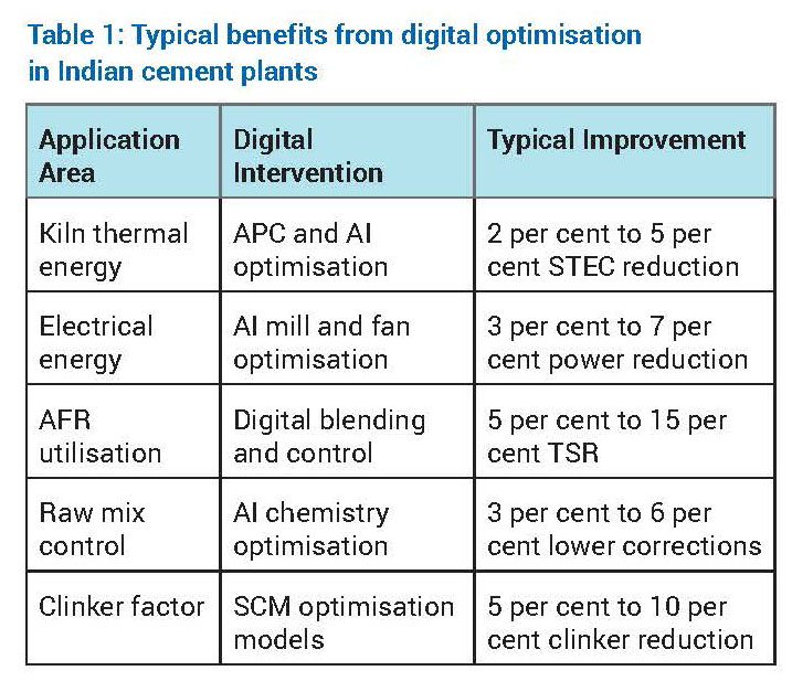
The kiln and calciner system accounts for approximately 60 per cent to 65 per cent of total energy consumption in an integrated cement plant. Digital optimisation focuses on reducing specific thermal energy consumption (STEC) while maintaining clinker quality and operational stability.
Advanced Process Control (APC) stabilises critical parameters such as burning zone temperature, oxygen concentration, kiln feed rate and calciner residence time. By minimising process variability, APC reduces the need for conservative over-firing. Artificial intelligence further enhances optimisation by learning nonlinear relationships between raw mix chemistry, AFR characteristics, flame dynamics and heat consumption.
Digital twins of kiln systems allow engineers to simulate operational scenarios such as increased AFR substitution, altered burner momentum or changes in raw mix burnability without operational risk. Indian cement plants adopting these solutions typically report STEC reductions in the range of 2 per cent to 5 per cent. - Electrical energy optimisation
Electrical energy consumption in cement plants is dominated by grinding systems, fans and material transport equipment. Machine learning–based optimisation continuously adjusts mill parameters such as separator speed, grinding pressure and feed rate to minimise specific power consumption while maintaining product fineness.
Predictive maintenance analytics identify inefficiencies caused by wear, fouling or imbalance in fans and motors. Plants implementing plant-wide electrical energy optimisation typically achieve
3 per cent to 7 per cent reduction in specific power consumption, contributing to both cost savings and indirect CO2 reduction.
Digital enablement of AFR
AFR challenges in the Indian context: Indian cement plants increasingly utilise biomass, refuse-derived fuel (RDF), plastic waste and industrial by-products. However, variability in calorific value, moisture, particle size, chlorine and sulphur content introduces combustion instability, build-up formation and emission risks.
Digital AFR management: Digital platforms integrate real-time AFR quality data from online analysers with historical kiln performance data. Machine learning models predict combustion behaviour, flame stability and emission trends for different AFR combinations. Based on these predictions, fuel feed distribution, primary and secondary air ratios, and burner momentum are dynamically adjusted to ensure stable kiln operation. Digitally enabled AFR management in cement plants will result in increased thermal substitution rates by 5-15 percentage points, reduced fossil fuel dependency, and improved kiln stability.
Digital resource and raw material optimisation
Raw mix control: Raw material variability directly affects kiln operation and clinker quality. AI-driven raw mix optimisation systems continuously adjust feed proportions to maintain target chemical parameters such as Lime Saturation Factor (LSF), Silica Modulus (SM), and Alumina Modulus (AM). This reduces corrective material usage and improves kiln thermal efficiency.
Clinker factor reduction: Reducing clinker factor through supplementary cementitious materials (SCMs) such as fly ash, slag and calcined clay is a key decarbonisation lever. Digital models simulate blended cement performance, enabling optimisation of SCM proportions while maintaining strength and durability requirements.
Challenges and strategies for digital adoption
Key challenges in Indian cement plants include data quality limitations due to legacy instrumentation, resistance to algorithm-based decision-making, integration complexity across multiple OEM systems, and site-specific variability in raw materials and fuels.
Successful digital transformation requires strengthening the data foundation, prioritising high-impact use cases such as kiln APC and energy optimisation, adopting a human-in-the-loop approach, and deploying modular, scalable digital platforms with cybersecurity by design.
Future Outlook
Future digital cement plants will evolve toward autonomous optimisation, real-time carbon intensity tracking, and integration with emerging decarbonisation technologies such as carbon capture, utilisation and storage (CCUS). Digital platforms will also support ESG reporting and regulatory compliance.
Digital pathways offer a practical and scalable solution for sustainable cement manufacturing in India. By optimising energy consumption, enabling higher AFR substitution and improving resource efficiency, digital technologies deliver measurable environmental and economic benefits. With appropriate data infrastructure, organisational alignment and phased implementation, digital transformation will remain central to the Indian cement industry’s low-carbon transition.
About the author:
Dr Y Chandri Naidu is a cement industry professional with 30+ years of experience in process optimisation, quality control and quality assistance, energy conservation and sustainable manufacturing, across leading organisations including NCB, Ramco, Prism, Ultratech, HIL, NCL and Vedanta. He is known for guiding teams, developing innovative plant solutions and promoting environmentally responsible cement production. He is also passionate about mentoring professionals and advancing durable, resource efficient technologies for future of construction materials.


Merlin Prime Spaces Acquires 13,185 Sq M Land Parcel In Pune

Adani Cement and Naredco Partner to Promote Sustainable Construction

Operational Excellence Redefined!

World Cement Association Annual Conference 2026 in Bangkok

Assam Chief Minister Opens Star Cement Plant In Cachar
Merlin Prime Spaces Acquires 13,185 Sq M Land Parcel In Pune
Adani Cement and Naredco Partner to Promote Sustainable Construction
Operational Excellence Redefined!
World Cement Association Annual Conference 2026 in Bangkok