Connect with us

Environment

Bharathi Cements has taken an initiative to optimise energy from the project stage itself

Published

on

Shares

Our goal of sustainability includes minimising breakdowns and achieving MTBF (Mean Time Between Failure) 160, achieving specific power consumption 78 Kwh/t cement, increasing PPC sales and fly ash addition in PPC, slag per cent in PSC, and also increasing alternate fuel substitution and AF substitution to reduce dependency on the State Electricity Board for Power, says BLN Murthy, Director – Works, Bharathi Cements. Excerpts from the interview.

How do you view the sustainability issues in the cement industry, in terms of energy efficiency?

Energy has been harnessed out of generated waste, and coal usage has been reduced proportionately by using alternate fuels such as processed chemical solid, liquid and semi-solid waste, waste wood, paint sludge, etc, from various industrial wastes. In 2012, we have consumed about 42,768 tonnes and in 2013 so far, we have consumed 29,810 tonnes of waste material received from various industries; fossil fuels have been proportionately reduced.

Efforts to substitute fossil fuels with waste have resulted in a reduction in the consumption of natural fuels by seven to eight per cent during the period 2012 and 2013. The usage of alternate fuels resulted in the elimination of the impact of hazardous waste on the environment. All waste material materials received from various chemical industries are being dealt with as per the guidelines of the Pollution Control Board.

Have you taken any water conservation measures?

Groundwater is 19.8 per cent of the total water withdrawn. The mines discharge water is being used for plantation and dust suppression systems. Efforts are on for a dry system of dust extraction instead of wet control measures, to minimise water consumption. A check dam has been constructed for storage of surface run-off water and to improve the ground water recharge.

Three farm ponds of one lakh M3 capacity have been developed and filled with mine discharge water. This water is used for plantation and dust suppression on haul roads during the summer season, so groundwater is not drawn too much.

A sewage treatment plant has been established and is in operation for the treatment of colony sewage water; the treated water is used for process applications in the cement plant. About 25 per cent of the total water requirement is met from STP recycling.

Brief us on the steps Bharathi Cement has taken to optimise energy efficiency.

Bharathi Cements has taken an initiative to optimise energy from the project stage itself. We have installed VFDs for both LT and HT drives for all process fans like pre-heater fans, RABH fans, raw mill fans, coal mill fans, cement mills fans and cooler fans, and we have installed high efficiency fans, low pressure drop cyclones in the pre-heater. We have also installed belt weighers for optimum loading of conveyors to avoid idle running of equipment, and have also provided VFDs whereever fans are operating with less than 75 per cent damper opening.

Have you used any high efficiency pollution control equipment?

In total, BCCPL has installed 120 unit bag filters, five bag houses, two RABH (reverse air bag houses) and two ESP (Electro Static Precipitators). We have installed pollution control equipment for each point of source emission in every process. With this good maintenance, we have achieved a zero discharge from emissions of the source point.

What are the steps you have initiated to reduce your carbon footprint?

In cement industries, power is a major factor that controls production costs. However, cutting power consumption is not the only option. At Vicat Sagar Cement, we have installed a 8.4 MW WHR system which is a co-generation system that can reliably supply about 30 per cent of the plant’s power needs at no extra fuel cost, reduce its carbon footprint and save precious water.

Large quantities of hot flue gases are generated from the cement industry, which is not useful for the cement manufacturing process. In cement plants, hot flue gases coming out of the pre-heater duct, cooler vent duct, cooler mid- tap can all be recovered to produce significant amount of electricity.

The oower generation process is based on the Rankine steam cycle. The steam generated in the boiler when expanded through a turbine, turns the turbine shaft, which in tandem is coupled to an electric power generator.

Depending on the carbon emission intensity of the grid power being replaced, this WHR will save more than 70,000 tonnes of CO2 a year.

The payback period for a waste heat recovery project is attractive. In fact, savings in production costs and emissions can lead to a return on investment after only a few years, depending on the cost of electricity and scale of the plant.

How do you assess the challenges on the logistics front?

We have taken the following steps to be more cost- efficient: Maximum utilisation of inbound fleet for outbound cement transport.

Use of GPS on trucks for better route planning , faster delivery and maximising number of trips to reduce cost and better utilisation of truck loads.

Efficient network planning using state- of-the- art optimisation tools.

Warehouse location chosen on the concept of minimum reverse transportation. Following the strategy of first mile bulk and last mile bag to reduce the overall cost Optimum inventory planning at warehouse to achieve zero damage targets. Laminated packaging with minimum pilferage.

Driver training for efficient and safe driving practices.Use of cross- docking to minimise handling and warehousing costs.

SUSTAINABILITY GOALS

  • Minimising breakdowns and achieving MTBF (Mean Time Between Failure) 160. – Achieved MTBF 114.42.
  • Achieving specific power consumption 78 Kwh/t cement – Sp. – Power consumption reduced to 79.5 Kwh /t cement
  • Increasing PPC sales to 55 per cent over total sales.- PPC sales achieved 49.5 per cent.
  • Increasing fly ash addition in PPC to 33 per cent – Fly ash addition in PPC increased to 30.38 per cent.
  • Increasing slag per cent in PSC to 40 per cent. – Slag in PSC increased to 36.6 per cent.
  • Increasing alternate fuel substitution to 30 per cent. – AF substitution increased to ten per cent.
  • Reducing dependency on State Electricity Board for power.- Thermal power plant work under progress.

GREEN INITIATIVES

  • Wet drilling and bag filter attachment for drilling machine to reduce dust emission during drilling.
  • Water spraying on the blasted material before loading.
  • Water sprinkling on haul roads.
  • Water spraying in limestone dump hopper and crusher.
  • Bag filters provided for all transfer points and collected dust hundred per cent utilised.
  • Water spray arrangement provided on belt conveyors to suppress dust.
  • Concrete roads provided in the plant to avoid dust during vehicle movement.
  • Reverse air bag house provided for the kiln and raw mill where the availability is one hundred per cent, no usage of water.
  • ESP provided for cooler vent gases and bag house for cement mills.
  • Roto packers and bag filters installed in cement pacing plant.
  • super sucker utilised for handling spillage materials to avoid dust.
  • Two road sweeping machines for cleaning the roads.
  • Neem plantation done all around boundary.
  • Trees planted all around material handling areas.

Electrostatic Precipitators

Electrostatic precipitators are installed for dust collection from the kiln cooler gases. ESPs are designed to deal mostly with coal- fired systems to collect dust in the flue gases. They are similar to the way an ionic breeze works. They take the incoming dirty air and pass it through a filtration device that purifies the air. Any solid particles left over will fall into a large storage container called a hopper and the clean air will be brought out.

Reverse air bag house – The hot gases from pre heater exhaust fan go to the bag house when the raw mill is not in need of it. When the raw mill is working, hot gases from the pre- heater exhaust fan partly go to heat the material in the raw mill. In the process, they cool down and thus, the final temperature and volume of gases is reduced when they enter the bag house. When the raw mill is not working, it can be by- passed and the gases from the pre- heater should be cooled down to 2400 C before they enter the bag house. The gases enter the bag house through the inlet duct and then are distributed to various modules through the hopper damper. The gases then are filtered through the bags. The dust gets separated on the inside of the bag and eventually falls in the hopper, and the clean gas enters the outlet duct through the outlet poppet damper. The gases from all the modules now enters the outlet duct and then flows to the exhaust fan.

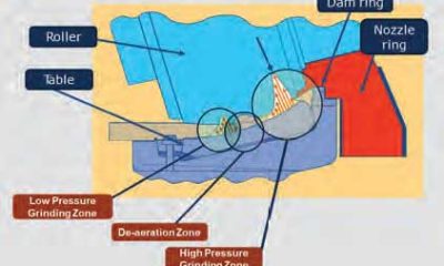
Unit bag filters and bag houses – Unit bag filters/ bag houses are working with dust laden air or gases enter through the hopper by suction or positive pressure. The heavier dust particles fall immediately into the hopper, while the light dust is distributed and deposited on the outside of the filter bags. When a uniform layer of dust has been formed on the surface of the filter bags, it is removed by a predetermined cycle of high pressure compressed air pulses. Cleaning efficacy is increased with the use of high efficiency venturi inserts that shape the initial pulse into a mass of air that travels down each filter bag, expanding it and dislodging the dust layer from its outer surface. The mass of air also draws the secondary air behind it, adding the downward air flow. The dust removed falls into the hopper and is discharged through the discharge valve.

How ESP works

Once all the previous items have been created, they are placed in a shell. This shell is basically the home of the precipitator. Almost all of the previous components are located in the shell which is typically comprised of carbon steel. It has holes on either side for the inlet and outlet ducts. The shell is also insulated to reduce the risk of condensation build- up.

Condensation will form when the flue gas which can leave the refinery at 2000 F, hits the inside of a cold precipitator. Also, condensation will interfere with the way in which the electrodes work and render them useless because condensation will collect on the walls and will begin to collect the particulate before it can be properly taken care of.

Hoppers are one of the major external elements. There are wires, piping and ductwork on the outside, but in the end, the hoppers collect the particulate. They, just like the shell, are typically made of carbon steel. Their main job is to collect what is rapped off the collecting plates. Once the particulate has been collected and the hoppers are full, rotary air locks and access doors are used to evacuate the hoppers. Below the hoppers , we have conveyors which convey the dust which will pull the particulate from the hoppers and bring it to a remote storage facility; or they have trucks driven underneath them that will physically truck the ash away. Inside the shell, the collecting electrodes are assembled parallel to the inlet duct.

The discharge electrode runs perpendicular to the inlet and collecting electrodes. As the flue gas comes out of the inlet and enters the precipitator the rigid mast discharge electrodes greet the flue gas and negatively charge them, allowing the positively charged plates that are running parallel to the inlet to collect the flue gas.

The other major external element is the rapper. It sits on top of the roof of the precipitator, and is programmed to deliver its powerful strike within a certain timed interval. The hammer end strikes the top of the collecting plates, making all the collected particulate fall into the hoppers below.

Electricity powers just about everything on the precipitator. It is used to power the electrodes, both positive and negative, and powers the rappers. It is also used to power the vacuum system on the evacuation of the hoppers, if the hoppers have this option. Most precipitators run auxiliary transformers to subsidise the amount of energy needed to keep the precipitators running.

Outlet duct is where the new clean gas will leave the precipitator. It gives the gas a final exit strategy from inside the shell where all the work had been previously done.

Continue Reading
Click to comment

Leave a Reply

Your email address will not be published. Required fields are marked *

Concrete

We engineer smarter systems to reduce waste

Published

on

By

Shares

Naveen Kumar Sharma, AVP – Sales and Marketing, Toshniwal Industries, talks about redefining instrumentation with customised, digitally enabled solutions engineered for harsh plant environments.

For over six decades, Toshniwal Industries has played a pioneering role in advancing process instrumentation for Indian manufacturing. In this exclusive conversation with Kanika Mathur, Naveen Kumar Sharma, AVP – Sales & Marketing, explains how the company designs kiln and grinding plant solutions tailored to the unique demands of the cement industry. As plants transition to higher AFR use and smarter automation, Toshniwal’s technologies offer greater reliability, accuracy and predictive insight.

Tell us how are your process instruments and condition monitoring system customised for cement kilns and grinding plant operations?
Toshniwal is a company with a legacy of over 65 years, and our experience has taught us that cement kilns and grinding units are fundamentally different in their operational demands. As an Indian company, we understand the unique requirements of Indian cement manufacturers. We work closely with our customers, engage deeply with their technical teams, and study operational challenges in real-time.
Based on these insights, we customise our solutions for both kiln and grinding applications. This tailoring is not just at a product level, but at a solution level—engineering design, instrumentation logic, and process optimisation. Our primary objective, for both the industry and our customers, is to reduce yield loss. Every customisation we implement is driven by this goal. We engineer smarter systems to reduce waste, improve consistency and increase plant reliability.
Ultimately, our solutions are built on an understanding that cement manufacturers require robust, practical and maintainable instruments. We design with this mindset so plants can operate more efficiently, with better control and higher profitability.

With the rising use of AFR, how do your solutions support thermal zone reliability and process time?
Our solutions are built around four core parameters: energy efficiency, yield loss reduction, product quality and environmental responsibility. These pillars drive our engineering decisions and define how our technologies support cement plants, especially as they adopt alternative fuels and raw materials (AFR).
We strongly believe in energy conservation. Every product we offer—whether for thermal monitoring, kiln control or flame optimisation—is engineered to improve energy performance. Reducing yield loss is another principle deeply embedded in our solutions, because production interruptions and material losses directly affect plant profitability and clinker quality.
We are also highly conscious of the end-product quality delivered by our customers to their markets. Consistency in burning, heat transfer, and thermal profiling directly influences clinker characteristics, and our instruments help maintain this stability.
Lastly, and most importantly, we care about the environment. We want to leave a greener world for the next generation. This mindset aligns with India’s digitalisation movement, advocated by our Prime Minister. Digital technologies are crucial for optimising AFR use, process stability, emissions and kiln efficiency. We are proud to contribute to this transition.
By optimising flame patterns, energy use, and pollution, our solutions deliver direct and indirect savings. Plants benefit from lower operational losses, reduced maintenance, and improved reliability, especially in pyroprocessing zones.

Tell us how do you address harsh environment challenges in cement plants, say dust, temperature, etc. with your sensor and monitoring?
This is a very important question because cement plants, steel plants, and power plants operate in extremely harsh environments. There are two major categories of specifications that we must respect while designing solutions: technical specifications and environmental specifications. Technical specifications relate to performance accuracy, measurement integrity, responsiveness and process safety. Environmental specifications, on the other hand, relate to high temperatures, heavy dust, humidity, vibrations and corrosive atmospheres. Our solutions are engineered to withstand both. We customise sensors, housings, mounting mechanisms and protective systems so that our instruments operate at 100 per cent functionality in harsh conditions. We ensure that the plant experiences minimal downtime from our systems. That is our engineering philosophy—solutions must work reliably in real-world environments, not just in ideal laboratory conditions.

What retrofit pathways do you offer for older cement lines to upgrade measurement and monitoring systems and how is the Indian market responding?
Every solution we provide is scalable and digitally adaptable. Technology evolves rapidly, and our offerings evolve with it. When we upgrade instruments or monitoring systems, we design them to integrate with existing plant infrastructure, so customers do not have to rebuild everything from scratch. Once our solution is installed, software upgrades or performance improvements can often be deployed without major cost. This ensures that customers continue to benefit from ongoing technological advancements. The Indian market has responded positively to this approach. Plant operators appreciate solutions that are future-ready and dynamic rather than static. Scalability helps them maintain competitiveness, extend asset life, and move toward smart manufacturing with confidence.

So how is your organisation leveraging digital technologies in your instrumentation portfolio for cement plants?
Digitalisation is at the core of every product we manufacture. We stand firmly behind the digital movement, not only because it represents efficiency, but because it is the direction in which the Indian industrial ecosystem is evolving. We deploy machine-vision technologies, advanced inline monitoring systems, and solutions capable of visualising the
inside of the furnace. These systems help reduce downtime, enable predictive asset management and provide actionable analytics to customers. All our technologies communicate seamlessly with Level 1, Level 2, and Level 3 automation. This allows integration across SCADA, DCS, ERP, and cloud ecosystems. Digitalisation for us is not an add-on—it is foundational to how our instrumentation is built.

What are your key innovation priorities to help Indian cement plant producers hit harder, higher substitution rates, lower emissions and smarter processing?
Sustainability is a national priority, and we are committed to supporting it. Our current portfolio already helps improve efficiency, reduce emissions, and support alternative fuel integration. But our innovation roadmap goes further. We are now developing specialised productivity-oriented software modules that will provide proactive alerts—not just alarms triggered after a fault has occurred. These modules will leverage artificial intelligence and machine learning to detect patterns early. The intention is to help plant teams take corrective actions ahead of time, reducing yield loss and environmental impact. Instead of informing the plant that a disruption has happened, the system will indicate that a disruption will happen, giving operators time to prevent it. We believe that within the next 12 to 18 months, we will launch these predictive solutions in combination with our instrumentation. When implemented, they will significantly improve decision-making, process stability and environmental performance across the Indian cement sector.

– Kanika Mathur

Continue Reading

Concrete

India donates 225t of cement for Myanmar earthquake relief

Published

on

By

Shares

On 23 May 2025, the Indian Navy ship UMS Myitkyina arrived at Thilawa (MITT) port carrying 225 tonnes of cement provided by the Indian government to aid post-earthquake rebuilding efforts in Myanmar. As reported by the Global Light of Myanmar, a formal handover of 4500 50kg cement bags took place that afternoon. The Yangon Region authorities managed the loading of the cement onto trucks for distribution to the earthquake-affected zones.

Continue Reading

Concrete

Reclamation of Used Oil for a Greener Future

Published

on

By

Shares

In this insightful article, KB Mathur, Founder and Director, Global Technical Services, explores how reclaiming used lubricants through advanced filtration and on-site testing can drive cost savings, enhance productivity, and support a greener industrial future. Read on to discover how oil regeneration is revolutionising sustainability in cement and core industries.

The core principle of the circular economy is to redefine the life cycle of materials and products. Unlike traditional linear models where waste from industrial production is dumped/discarded into the environment causing immense harm to the environment;the circular model seeks to keep materials literally in continuous circulation. This is achievedthrough processes cycle of reduction, regeneration, validating (testing) and reuse. Product once
validated as fit, this model ensures that products and materials are reintroduced into the production system, minimising waste. The result? Cleaner and greener manufacturing that fosters a more sustainable planet for future generations.

The current landscape of lubricants
Modern lubricants, typically derived from refined hydrocarbons, made from highly refined petroleum base stocks from crude oil. These play a critical role in maintaining the performance of machinery by reducing friction, enabling smooth operation, preventing damage and wear. However, most of these lubricants; derived from finite petroleum resources pose an environmental challenge once used and disposed of. As industries become increasingly conscious of their environmental impact, the paramount importance or focus is shifting towards reducing the carbon footprint and maximising the lifespan of lubricants; not just for environmental reasons but also to optimise operational costs.
During operations, lubricants often lose their efficacy and performance due to contamination and depletion of additives. When these oils reach their rejection limits (as they will now offer poor or bad lubrication) determined through laboratory testing, they are typically discarded contributing to environmental contamination and pollution.
But here lies an opportunity: Used lubricants can be regenerated and recharged, restoring them to their original performance level. This not only mitigates environmental pollution but also supports a circular economy by reducing waste and conserving resources.

Circular economy in lubricants
In the world of industrial machinery, lubricating oils while essential; are often misunderstood in terms of their life cycle. When oils are used in machinery, they don’t simply ‘DIE’. Instead, they become contaminated with moisture (water) and solid contaminants like dust, dirt, and wear debris. These contaminants degrade the oil’s effectiveness but do not render it completely unusable. Used lubricants can be regenerated via advanced filtration processes/systems and recharged with the use of performance enhancing additives hence restoring them. These oils are brought back to ‘As-New’ levels. This new fresher lubricating oil is formulated to carry out its specific job providing heightened lubrication and reliable performance of the assets with a view of improved machine condition. Hence, contributing to not just cost savings but leading to magnified productivity, and diminished environmental stress.

Save oil, save environment
At Global Technical Services (GTS), we specialise in the regeneration of hydraulic oils and gear oils used in plant operations. While we don’t recommend the regeneration of engine oils due to the complexity of contaminants and additives, our process ensures the continued utility of oils in other applications, offering both cost-saving and environmental benefits.

Regeneration process
Our regeneration plant employs state-of-the-art advanced contamination removal systems including fine and depth filters designed to remove dirt, wear particles, sludge, varnish, and water. Once contaminants are removed, the oil undergoes comprehensive testing to assess its physico-chemical properties and contamination levels. The test results indicate the status of the regenerated oil as compared to the fresh oil.
Depending upon the status the oil is further supplemented with high performance additives to bring it back to the desired specifications, under the guidance of an experienced lubrication technologist.
Contamination Removal ? Testing ? Additive Addition
(to be determined after testing in oil test laboratory)

The steps involved in this process are as follows:
1. Contamination removal: Using advanced filtration techniques to remove contaminants.
2. Testing: Assessing the oil’s properties to determine if it meets the required performance standards.
3. Additive addition: Based on testing results, performance-enhancing additives are added to restore the oil’s original characteristics.

On-site oil testing laboratories
The used oil from the machine passes through 5th generation fine filtration to be reclaimed as ‘New Oil’ and fit to use as per stringent industry standards.
To effectively implement circular economy principles in oil reclamation from used oil, establishing an on-site oil testing laboratory is crucial at any large plants or sites. Scientific testing methods ensure that regenerated oil meets the specifications required for optimal machine performance, making it suitable for reuse as ‘New Oil’ (within specified tolerances). Hence, it can be reused safely by reintroducing it in the machines.
The key parameters to be tested for regenerated hydraulic, gear and transmission oils (except Engine oils) include both physical and chemical characteristics of the lubricant:

  • Kinematic Viscosity
  • Flash Point
  • Total Acid Number
  • Moisture / Water Content
  • Oil Cleanliness
  • Elemental Analysis (Particulates, Additives and Contaminants)
  • Insoluble

The presence of an on-site laboratory is essential for making quick decisions; ensuring that test reports are available within 36 to 48 hours and this prevents potential mechanical issues/ failures from arising due to poor lubrication. This symbiotic and cyclic process helps not only reduce waste and conserve oil, but also contributes in achieving cost savings and playing a big role in green economy.

Conclusion
The future of industrial operations depends on sustainability, and reclaiming used lubricating oils plays a critical role in this transformation. Through 5th Generation Filtration processes, lubricants can be regenerated and restored to their original levels, contributing to both environmental preservation and economic efficiency.
What would happen if we didn’t recycle our lubricants? Let’s review the quadruple impacts as mentioned below:
1. Oil Conservation and Environmental Impact: Used lubricating oils after usage are normally burnt or sold to a vendor which can be misused leading to pollution. Regenerating oils rather than discarding prevents unnecessary waste and reduces the environmental footprint of the industry. It helps save invaluable resources, aligning with the principles of sustainability and the circular economy. All lubricating oils (except engine oils) can be regenerated and brought to the level of ‘As New Oils’.
2. Cost Reduction Impact: By extending the life of lubricants, industries can significantly cut down on operating costs associated with frequent oil changes, leading to considerable savings over time. Lubricating oils are expensive and saving of lubricants by the process of regeneration will overall be a game changer and highly economical to the core industries.
3. Timely Decisions Impact: Having an oil testing laboratory at site is of prime importance for getting test reports within 36 to 48 hours enabling quick decisions in critical matters that may
lead to complete shutdown of the invaluable asset/equipment.
4. Green Economy Impact: Oil Regeneration is a fundamental part of the green economy. Supporting industries in their efforts to reduce waste, conserve resources, and minimise pollution is ‘The Need of Our Times’.

About the author:
KB Mathur, Founder & Director, Global Technical Services, is a seasoned mechanical engineer with 56 years of experience in India’s oil industry and industrial reliability. He pioneered ‘Total Lubrication Management’ and has been serving the mining and cement sectors since 1999.

Continue Reading

Trending News