Product development
Refractories Selection for Cement Industry

The appropriate refractory selection for the stationary section improves the kiln uptime, which, in turn, has favourable impact on the refractory life as well as operating efficiency, says I N CHAKRABORTY.
Refractory selection is the most important step for the maximisation of its performance. The major deciding factor for refractory selection is the working or operating environment where the refractory would be used.
The working environment, in general, is defined by the following parameters:
- Operating temperature
- Chemical condition
- Chemical nature of solid/ liquid, i.e., acidic or basic, in contact with refractory
- Characteristic of gaseous environment
- Thermal shock
- Mechanical stressv
- Abrasion
All the aforementioned parameters are not relevant for each industrial application. Identification of critical parameters, for a given working environment, is vital for refractory life maximisation at optimal cost. Once the critical operating parameters are identified, the refractory should be so selected that it can withstand the operating conditions for the stipulated life span. Operating Conditions
For the cement industry, the operating conditions for various parts of the kiln system can be deduced Ref. Figure 1. The concentration of raw meal constituents and the new phases formed therefrom, at different stages of the processing, are depicted by the width of the coloured bands. The X and Y axes indicate the dwelling time of the raw meal and temperature at each stage of the processing, respectively. It is evident that for a ‘theoretical’ raw meal, i.e., a mix of limestone, quartz, clay and some lateritic material, the operating condition in the cement kiln is not very severe, except for the burning zone, where the temperature is as high as 1,4500C and the liquid content of the feed material would be in the range of 25-27 per cent.
By the time the raw mix attains 9000C, the limestone present in raw meal is decomposed into CaO, clay is dehydrated and quartz undergoes polymorphic transformation. Simultaneously, formation of some of the cement constituents, e.g., C2S and C3A, commences. None of these reactions has any adverse impact on the refractory. As the temperature rises to ~1,4000C, the liquid phase forms. At the maximum operating temperature, which is ~1,450 0C, the liquid phase concentration is 25-27 per cent. On cooling, C3S and C4AF precipitate out from the melt. As the clinker cools down, the reactivity of the mass reduces; i.e., the refractory is not chemically affected. However, the clinker, on cooling, becomes abrasive and has a tendency to erode the refractory. The situation worsens in the modern pre-heater – pre-calciner kilns, where the clinker is dustier. The cooler refractories which include cooler take-off duct, bull nose and tertiary air ducts are impinged upon by dust-laden gas.
Thus, except for the burning zone, the operating condition of cement kiln ‘apparently’ is of moderate severity, at least from the chemical attack point of view. The temperature in the non-burning zone part of the kiln system is not high enough for reaction between the aluminous refractory and lime-bearing raw meal/clinker. Chemically "non-compatible", i.e., alumino-silicate refractories in basic environment, hence, suffice for the majority part of the kiln system Ref. Figure 2.
But in reality the situation does not remain so simple owing to volatile cycle in the cement kiln and its accessories. Volatile Cycle
The reality is raw meal and fuel bring in potassium, sodium, sulphur and chlorine in the cement rotary kiln system. These constituents combine to form a varied range of alkali compounds. The nature of compounds formed, i.e., the ones available in the kiln environment, is determined by the alkali sulphur ratio (ASR), which is expressed as per the following relationship. ASR is calculated based on the molar concentration of the constituents in the kiln gaseous environment, 
When,Q = 1 KCl and K2SO4 in
the environment
Q > 1, KCl and K2SO4 as
well as free SO3
Q < 1, KCl and K2SO4 as
well as free K2O
The situation worsens when alternate fuel is used, since their alkali and chlorine concentrations are significantly higher compared to the conventional ones. Table I reports the melting point of the compounds which form in the kiln environment. Since the melting points of the newly formed alkali compounds are significantly lower than the maximum operating temperature of the kiln, part of these compounds partially vapourise in the kiln and travel along with the flue gas towards the kiln inlet areas, whereas the rest escape the kiln system by combining with the clinker. The alkali bearing compounds in the flue gas get deposited on the incoming raw meal at the corresponding freezing point of these alkali compounds.
The alkali-enriched raw materials travel back in the kiln and the aforementioned process gets repeated. Since the chloride compounds have lower melting point than the sulphates, they have the ability to travel further back in the kiln system, compared to the sulphur-bearing compounds. Owing to this cycling process, the kiln environment becomes richer in alkalis, compared to their concentrations in the raw meal. The volatile constituents usually get enriched by following factors:
R2O: 5 times
SO3 2-: 3-5 times, and
Cl: 80-100 times
Owing to the self-enrichment phenomenon, raw meal chemistry does not indicate the true chemical environment of the kiln. Build-Up Formation
While these volatile compounds travel with the flue gas and interact with the incoming raw meal, they either get deposited on the incoming raw meal or on the refractory surface. Since the deposited alkali compounds are in semi-fused state at this temperature, Incoming raw meal sticks to the alkali-coated refractory surface. This phenomenon is usually known as "build-up" formation. Build-up formation occurs where the temperatures, as expected, are in the range of the freezing points of the alkali compounds (Table I). The kiln inlet, smoke chamber and lower riser ducts are the most vulnerable areas for build-up formation since the operating temperatures of these regions fall in the range of melting point of the alkali compounds. It is, hence, evident that the build-up problem of the kiln inlet region originates from the cement manufacturing process, not from the refractory. Figure 2: Typical Refractory Choice for
Different Parts of the Rotary Kiln System.
The-build up hinders the flow of raw meal and the production often needs to be stopped for their dislodgement, which is either by thermal or mechanical shock. Both these methods of build-up dislodge-ment put stress on the refractories and may cause premature failure. Solution of Build-Up through Refractory
There exists a solution for the build-up problem through refractory. The build-up can be minimised, if not eliminated altogether, by using a SiC-based castable, wherever such problem exists. The SiC content of the formulation is governed by the exact nature of the kiln environment. While designing the refractory formulation, the stability of SiC in a chlorine-rich environment must be considered. The basic mechanism for build-up resistance is by virtue of vitreous phase formation on the refractory surface, via following reactions:
- SiC (s) + 3/2O2 (g) = SiO2 (s) + CO (g) (l)
- SiO2 (s) + Na2CO3 (l) = Na2SiO3 (Glass) + CO2 (g), and
- SiO2 (s) + Na2SO4 (l) + 2C (s) + 3/2O2 (g) = Na2SiO3 (Glass) + SO2 (g) + 2CO2 (g)
Figure 3: Abrasion Resistances of Some of the Commercial
Products Measured by ASTM C 704.
Since the glassy surface is slimy, the adherence of build-up on the refractory surface is weak and hence, falls off under its own weight or by light mechanical shock. The elimination of build-up, in SiC-based formulations, is by an unconventional process, i.e., by allowing the refractory to react with the environmental constituents. Since the build-up adherence is a physical phenomenon, we recommend SiC-based castable instead of bricks, as it offers lesser foothold compared to bricks owing to lesser number of joints. Alkali Bursting
No refractory is impervious and hence, alkali compounds, present in the kiln environment, not only travel to the cooler part of the kiln, but also travel to the cold face of the refractory through the inherent pores present in them. While travelling, the alkali compounds can interact with the refractories. The resultant of the alkali-refractory interactions are as under:
Chemical reaction with refractory, i.e., formation of new compounds, and/or
Physical interaction – i.e., alkali impregnation, which leads to densification of brick texture resulting in loss of structural flexibility. This leads to refractory failure by thermal spalling.
The refractory cracks vigorously, which is normally termed as ‘alkali bursting’. Alkali bursting occurs due to formation of following feldspathic compounds by reaction between alkali and alumino-silicate refractories. It is evident that formation of all these feldspathic compounds is expansive in nature, which induces stress in the refractory, leading to their cracking.
Kaliopholite (KAS2): (V = + 29%)
– Alumina {(K/Na)2A}: (V = + 29%)
Kalisite {(K/Na)AS2}: (V = + 17%)
Leucite (KAS4): (V = + 10%)
Orthoclase (KAS6): (V = + 6%)
Both the phenomena, i.e., physical as well as chemical attack of alumino-silicate refractories by alkali, can be overcome, if SiC is incorporated in the refractory formulation. It is a common knowledge now that SiC-bearing refractories, when used in alkali environment, see a glassy layer forming on their surface, which acts like an impervious layer and prevents alkali penetration into the bulk of the refractory. Refractories for Kiln Downstream
In the downstream, the clinker becomes more abrasive as it becomes cooler and volatile components may still be in the atmosphere. Temperature fluctuation, i.e., thermal shock, always remains an issue in the tip-casting area. For areas with relatively higher temperature, i.e., the locations where operating temperature is higher than the melting point of the alkali compounds, alkali resistance in refractories is desirable. In short, refractories, in all the areas of downstream, should be resistant to abrasion. For some locations, additional features like thermal shock as well as alkali resistance would be required. The areas which require only abrasion resistance, e.g., tertiary air ducts, aluminous refractories with high resistance to abrasion are recommended. The abrasion resistances for some of the commercial products are illustrated in Figure 3.
Prior to the development of abrasion resistance castable, 90% Alumina Low Cement Castable (LCC) has been the most abrasion resistance refractory. The data (Figure 5) reveals that abrasion resistance of this new abrasion resistant castable is over three times better than that of 90% Alumina LCC. Field trial results indicate significant improvement in performance while using the newer formulation in high abrasion areas of cement kiln. Refractories for Burning and Transition Zones
The refractory selection process in the kiln burning and transition zones differ significantly compared to the static part of the kiln. Cement kiln burning zone bricks wear due to the combined effect of chemical, thermal and mechanical factors. Chemical Factor – Raw Meal
Cement raw meal compositions are normally defined by certain moduli, which are primarily ratios of various chemical constituents present in the raw meal.
Lime Saturation Factor (LSF) = CaO / (2.8SiO2 + 1.2Al2O3 + 0.65Fe2O3). The LSF controls the ratio of C3S to C2S in the clinker. A clinker with higher LSF implies C3S content of clinker is higher.
Silica Ratio {(SR) = SiO2 / (Al2O3 + Fe2O3)}, indicates the amount of liquid phase in the clinker; lower the SR, higher is the liquid content during the burning process. When SR exceeds 3, liquid phase content is low and burning temperature becomes high, i.e., high kiln load, which has adverse effect on the refractory.
When LSF and SR are high, or quantity of MgO and alkali are low, burning becomes more difficult, i.e., refractories suffer.
Alumina Ratio (AR) = Al2O3 / Fe2O3, it characterises the composition of the melt; low AR implies low viscosity of clinker liquid phase. When AR < 1.5, melt viscosity decreases, and the higher is the possibility of infiltration of liquid in the refractory. If AR exceeds 2.5, e. g. for white cement, melt viscosity increases and the burning condition becomes difficult.
It is, hence, apparent that raw meal chemistry has a significant role in determining quantity as well as quality of liquid, which, in turn, determines the firing condition and the ultimate refractory performance. Thermal Factor
Figure 4 illustrates the temperature of the burning zone refractory during the kiln rotation. The kiln lining is permanently subjected to thermal stresses due to differences in the temperature under the clinker bed and the open atmosphere. During each rotation, i.e., at a frequency of two-four times per minute, the refractory sees a temperature variation of over 600 ?C.
Thermal shock, thus, is an inherent part of rotary kiln operation. At the kiln inlet, temperature changes can even be higher due to the secondary air from the cooler.
Thermal shock resistance of bricks is increased by
??igh mechanical resistance
??igh thermal conductivity
??ow elasticity modulus
??ow thermal expansion coefficient
Thermal shock resistance, which can be approximated by the ratio of CCS and shear modulus, increases with the decrease of elastic modulus. When the aforementioned ratio exceeds 5×10⁻³, thermal shock resistance is expected to be good. The bricks for transition and burning zones should be so selected that they meet these criteria. Mechanical Forces
As the kiln shell gets older, ovality and kiln shell distortion becomes the major cause of concern and has adverse effect on refractory life. The kiln ovality is defined by the following equation:
Ovality () = (4/3) x D2 x s x 100 (%), where
s = Greatest deflection value from the shell test and
D = Kiln diameter
Increase of kiln ovality, as expected, increases the stress on the refractory lining. In addition to kiln shell ovality, the refractories are stressed during each rotation (Figure 5). The major mechanical stress is generated in the kiln tyre zones due to rotation of the kiln shell and its elastic flexing, i. e., squeezing.
Stress on the refractories in kiln, thus, originates from thermal shock, kiln shell ovality and thermal expansion. Bricks with higher elasticity, i.e., low elastic modulus, resist the mechanical stress better. Coating Formation
The formation of coating on the refractory lining is attributable to formation of highly viscous calcium ferrite and calcium aluminate compounds followed by their solidification on the refractory surface.
The coating, thus, forms due to interaction between the liquid formed in the raw meal during burning and brick constituents. A stable coating in the burning zone protects the refractories from thermal shock as well as prevents chemical interaction with the raw meal at elevated temperature. Usually the coating in the transition zone is not very stable, i.e., it falls off frequently. As a fallout of the same, in general, the average refractory surface temperature in the transition zone is higher than that of the burning zone. Also, thermal stress is the highest in the uncoated transition zones. In general, the refractories undergo highest thermal shock during operation interruptions and hence, it must be minimised.
Formation of stable coating on the brick, thus, is highly desirable. For the formation of stable coating, various modulii defined earlier should be optimised so that the liquid formed is viscous and the burning condition is not hard. If the liquid formed is low in its content as well as in viscosity, adherence on the brick surface, i.e., coating formation, is poor.
Additionally, when the liquid viscosity is low, formed liquid penetrates the refractory pores, causing textural densification leading to spalling. In the absence of coating, bricks wear out due to various reasons, which of course depend on the brick quality. For optimum operation LSF, SR and AR should be in the range of ~ 0.96, 2.2-2.6 and 1.5-2.5, respectively. These parameters ensure ease of burning, optimised liquid quantity with appropriate viscosity for stable coating formation Bricks for Burning and Transition Zones
From the chemistry point of view, magnesite bricks are ideally suited for the cement kiln burning and transition zones. Magnesite bricks, however, are too vulnerable owing to their poor spalling resistance arising out of their high expansion coefficient. As evident from the earlier section, the stress absorbability is the primary selection criterion for both transition as well as burning zones. The selected bricks, hence, should be highly elastic. The desired level of elasticity cannot be provided by magnesite.
Appropriately designed mag-chrome bricks are ideal, though they are vulnerable to frequent change in kiln redox condition, for rotary kiln burning zone applications, since the coating adherence on such bricks is excellent. The environmental concern, owing to the formation of hexavalent chrome, especially in the alkali-rich environment following the reaction, has caused their decline in the cement kiln application.
MgO. Cr2O3 + 2 Na / K = (Na / K)2(CrO4)
Mag-Al bricks or zirconia containing magnesia bricks yield low elastic modulus i.e., high structural flexibility, and hence offer excellent resistance to mechanical stress. In general, Mag-Al bricks show poor coating adherence capability. In the absence of coating, they are chemically vulnerable owing to the formation of C12A7, when the temperature exceeds 1,350?C. Better chemical compatibility, however, is achieved by increasing the magnesia content to the level of ~ 95 per cent and/or by basing the product on sinters of natural magnesite of specific grade.
Magnesia-Hercynite (FeO.Al2O3) bricks, which show equally high tendency for coating formation as Mag-Chrome bricks, also are less sensitive to thermal as well as mechanical stresses. These bricks are a good balance between environmental concern and performance.
The exact selection of burning and transition zone bricks is based on the condition prevailing in the specific kiln.
Generic alumino-silicate refractories suffice in majority of locations, except for upper as well as lower transition zones and burning zone. Such refractories are a definite choice for upper cyclones since they are not exposed to high abrasion or alkali attack. Lower cyclones and kiln inlet areas, however, may require special refractories, e.g., SiC-based formulations or its derivatives, when alkali concentration in the kiln atmosphere is high. Downstream of burning zone mainly requires refractories which resist abrasion as well as thermal shock. Alkali resistance sometimes is desirable for kiln downstream applications. For areas with only abrasion, e.g., in tertiary air ducts, abrasion resistance castables are recommended. For rest of the downstream locations, e. g., cooler bull nose, cooler bench and cooler take-off duct, either abrasion resistant or SiC-based castable is recommended, depending on the exact operating conditions.
Burning and transition zone refractory selection is primarily determined by raw meal characteristic and exact kiln operation condition. The choice, however, is limited to non-chrome spinel bricks. About the authorDr. Indra N. Chakraborty is a ceramic engineer from BHU. He holds a doctorate from Illinois University has done extensive work in refractories. He is presently President R&D and QPC Calderys India Refractories Limited.


Table I The Melting Points of the Volatile Compounds Formed in the Rotary Kiln System.


Our strategy is to establish reliable local partnerships

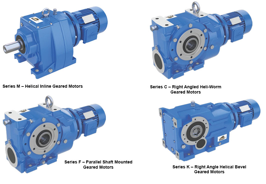
Power Build’s Core Gear Series

Compliance and growth go hand in h and

Turning Downtime into Actionable Intelligence

FORNNAX Appoints Dieter Jerschl as Sales Partner for Central Europe
Our strategy is to establish reliable local partnerships
Power Build’s Core Gear Series
Compliance and growth go hand in h and
Turning Downtime into Actionable Intelligence