Connect with us

Economy & Market

Failures of ?Gearbox and Drives?

Published

on

Shares

It is a pain area for the plant management team when the gear drive fails and it is more difficult to arrive at the correct cause of failure. S Sengupta & A Ray Chowdhury from Sprat Consultancy elaborates on some of the common causes of failures, also suggests remedial measures.

The idea of putting pen to paper regarding gear drives seems to be a daunting task. One is apprehensive as to where to begin and to what degree to write is a nerve racking proposition as majority of the readers are qualified, sound practical engineers who are associated with industrial plants such as cement, power, metals, etc. Experience confirms that a meaningful insight on the subject requires around three working days and if fourth day could be added by way of site visit with discussions on practical problems, works out a ?win-win? situation for all.

An endeavour is however being made to jot down some thoughts that may serve as pre curser from selection to use of drives. The order of narration is not sacrosanct and not all encompassing. It is just a brief write up on few attributes hoping it will provoke the mind of concerned personnel be it users or project/technical personnel. Use of gear drives in a system does not imply just operational; it encompasses what happens within a drive train and requirements to achieve desired performance life hence design life.

In many instances over the past 38 years, we have come across failures in drives caused by lack of insight or foresight or lack of correct data or its understanding during selection of drive. A common failure, but not frequent, is lack of perception of what all is to be handled &/or power required to drive the system.

An example that readily comes to mind is in a greenfield cement plant around early 1980s: the external consultant confirmed motor power, application, operating hours per day, etc. and wanted a drive with a safety factor (SF) of 2.5. This particular gear drive was 1 amongst 65 others. It was the only one that was prone to frequent failure to the tune of once every three months. Review of actual operating data confirmed actual power consumed was 40 per cent higher than confirmed during project design & planning leading to premature failures.

Another instance of premature failures observed in a cement plant in Western India of a twin drive bucket elevator where input drive was through fluid coupling. After a year of satisfactory operation failures commenced with regularity in one of the gear drives in the arrangement. As they were imported gearboxes not much hue and cry was raised initially. Replacements from two indigenous producers also failed in the same manner and frequency leading to a pantomime at the plant. Analysis of the drive arrangement confirmed power consumed by individual drives differed by over six per cent. In such a scenario, failure was inevitable and plant further confirmed that after a year one drive motor had burnt out requiring rewinding. Rewinding is common accepted process but what is equally important is that in a twin drive synchronisation of input power is of utmost importance of within two per cent variance. Since synchronise of input power no further failures occurred over a decade.

There are many other instances of failures we often recollect as observed over the last four decades. In all instances failures have taken place for:

  • Incomplete or inadequate clarity of specification at initial stage.
  • Lack of appreciation of specification, which is more dangerous.
  • Hypothesis by OEM of likely operational parameters viz a viz specification thus incorrect supply.
  • Augmenting capacity after year/s of use and not sharing data with supplier or supplier not appreciating information conveyed which must be well defined.

In short whatever are the circumstances in life (we consider gear drives also a form of life) it takes two to speak the truth to form an understanding and thus realisation. In the field of machine dynamics the same applies; dialogue between user and supplier must be continual and without inhibition or prejudice. In other words partnership is required with frank exchanges, irrespective of how insignificant the information may appear, to eliminate misgivings consequently failures.

The more this realisation dawns on all in a B2B scenario and quicker the better for all concerned resulting in reliability of operations. Failures are phenomena that cannot be totally ruled out even with best intentions of user and supplier. Any failure, irrespective of its occurrence, within or beyond the warranty period or after extended period of use is relevant at all times towards better and improved designs unless failure occurs beyond design life of rolling elements. This information should be shared with factual details unambiguously.

It is common for most designers to design critical drives, irrespective of type/size &/or application considering a life of 100,000 hours for gears/pinions and around 60,000 hours for bearings. Indirectly, to a large extent, bearing life sets the set point for case hardened and ground gears/pinions although theoretically it has an infinite life.

The question therefore arises why premature failures occur within warranty period or shortly thereafter. One of the primary reasons for failure beyond warranty period is governed by the quality of lubricating oil being used. Often quality is misunderstood with viscosity grade. Quality per ?say? has no relation to viscosity grade; it refers to the cleanliness of the oil.

  • Lubricating oil needs to be maintained clean and the desired level is NAS6 for industrial application other than turbine drives. This value of NAS6 also applies to wind mill drives and speed increasers as opposed to high speed drives. The cleanliness value of NAS6 does not readily register with users and to some extent with suppliers of gear drives. To put it mildly, check oil directly from a sealed barrel supplied by OEM for its NAS value and you will invariably find it anywhere around NAS10 or worse. Do not assume it happens only with indigenous supplies as it is far from the truth. Checks conducted with top brand sealed oil drums, indigenous or imported, confirm this is normal and common.
  • The onus thus lies with users to appreciate why oil cleaning is required and how does it improve the performance as well as life of the gear drive. It is safe to conclude, which concurs with our observation, that organisation which maintains lubricating oils health is less prone to premature failures. They invariably enhance the life of their drives by any where up to 30% higher than others for same drive conditions. This phenomena can be observed in an organisation &/or plant to plant operations but sadly data and findings are rarely pooled.
  • Another disturbing fact is often lubricating oil is procured on price consideration only and neglect issues such as scuffing, scoring, wet-ability etc properties.
  • Cost differential between normal mineral oil containing higher levels of sulphur and phosphorous in relation to vacuum distilled mineral oils is around 75-80 per cent more but the usable life of oil, if cleanliness maintained around NAS6, will justify the extra cost as life will be minimum double of normal mineral oil. A cement plant in Eastern India has continually achieved life of three times that of normal mineral oils there by not only resulting in huge savings to the organisation by way of less oil consumption and frequent shutdowns for changing oil.
  • Do note, normal mineral oils with higher levels of sulphur and phosphorous have an greater affinity to absorb moisture from the atmosphere leading to formation of sulphuric & phosphoric acids; both are very harmful towards life of bearings, seals and last but not least internal preservative paints applied to gearbox housing walls adding to further contamination.
  • A question we need to ask our self, as buyers we seek guarantee and warranty at the drop of a hat then why not for lubricants used?
  • Another cause of failure beyond warranty period is the upkeep of breathers, seals, etc. along with external surface of the gear drive. Often it is neglected resulting in breathers getting choked &/or become an ingress point for dirt when drive is stopped. As a result we have oil seal leakages and oil contamination leading to premature failures. Such instances are quite common in conveyor drives of cement grinding section or packing plant, coal handling conveyors, etc. An excuse we at times come across for not maintaining minimal level of cleanliness is, it is not a critical drive! The same excuse is also conveyed when the gearbox is covered with dust. What fails to be appreciated by the user is damage is taking place to investments and it can has a cascading effect.
  • There are numerous other instances of failures beyond warranty period but this is nether the forum or place to address these issues.
  • Failures during warranty period can be generally summed up under following heads as trends prevailing in gear design are to raise power levels till it does not result in a failure while decreasing volumes thus weight leading to increasing problems of heat dissipation:
  • Faulty or inadequacy of design
  • Incorrect selection & use of materials for manufacture
  • Incorrect selection of bearing
  • Manufacturing errors
  • Heat treatment errors
  • Assembly errors
  • Fluctuating or incorrectly defined operating parameters
  • Variants from original specification supplied &/or contaminates
  • Use of improper or incorrect quality of lubricant

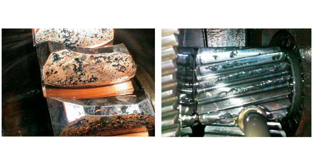
Very rarely only one of the above mentioned causes account for failure to gear drives thus understanding and assessing gear damage requires in-depth knowledge of:

  • Gear contact patterns
  • Gear tooth failure types and probable causes
  • Bearing failure types with probable reasons
  • Lubricating oils
  • Oil flow within the gear drives be it splash or forced lubrication, etc.

It is not feasible to go through all these aspects in depth through this short article but to create awareness towards minimising risks of premature failures. We as such recommend use of following documents as a starting point to improve performance of gear drives thus overall operations of a plant. The documents relate to what needs to be communicated to the prospective seller and what in return you must get from them without fail.

Info. to be given By gearbox manufacturer

1.With offer for critical drives:
Design calculation in details for safety wrt wear & strength confirming material grade, etc.

2.Along with general arrangement (GA) drawing after placement of order:

  • GA drawing for all gear units, unless otherwise agreed upon, that gives full details of all manufactured part numbers and full nomenclature of proprietary parts including prefix and suffix, if any.
  • Number of teeth of each pinion and gear to facilitate vibration analysis. ?Spare parts list that can be correlated with GA drawing & the part number.
  • Approximate weight of gearbox.
  • Direction of rotation of input and output shafts.
  • GD? value of critical drives.
  • In case of pressure lubrication system water and oil flow rates with pressure range. Should also specify water and oil temperature gradient envisaged between inlet and outlet.
  • In case of cooling coil water flow rate and temperature gradient envisaged between inlet and outlet.
  • Details of interlocking, if any required to be ensured.

Note:

  • Your requirements of above data should be incorporated in your tender or enquiry or most major manufacturers will refuse to comply with the request at a later date.
  • Data of number of teeth will not only facilitate vibration analysis personnel but may facilitate in rationalising spares inventory if similar gearboxes are available in the plant or if same series gearboxes are installed of sizes that are just smaller or bigger than that on order.
  • Information to be given By a client

Following information are required to be furnished along with enquiry to finalise drive:

1. Prime mover – confirm type with full details like kW, rpm, Hz, type etc:

  • Motor
  • Turbine
  • I.C. engine

2. Input coupling – specify which:

  • Pin bush type flexible
  • Geared coupling
  • Fluid coupling
  • Bibby coupling
  • Tyre coupling
  • Any other than that mentioned above?

Note:

  • If coupling is not in the scope of gearbox supplier then its type, make, bore with tolerance of half to be mounted on gearbox are to be furnished.
  • Coupling in scope of gearbox OEM then confirm motor shaft diameter & tolerance.

3. Input through belt pulley drive – confirm following:

  • Pitch circle diameters of pulleys?
  • Direction of rotation of input shaft looking towards it?
  • Type of pulleys?

Note:
Provide sketch showing disposition of pulleys with respect to gearbox with dimensions in vertical and horizontal plane.

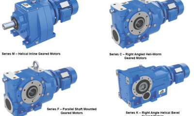
4. Type of gear drive:

  • Configuration of gearbox required i.e. helical, bevel/helical, RH, LH etc.
  • Operating hours per day?
  • Minimum and maximum ambient temperature where it is installed?
  • Place of installation i.e. open space, small confined area or large workshop?
  • Environmental condition e.g. normal, dusty, etc.

Note:
Mention if any other speciality is required in the drive.

5. Output coupling – specify which:

  • Pin bush type flexible
  • Geared coupling
  • Any other than that mentioned above?

Note:

  • If coupling is not in the scope of gearbox supplier then its type, make, bore with tolerance of half to be mounted on gearbox are to be furnished.
  • Coupling in scope of gearbox OEM; confirm machine shaft diameter & tolerance.

6. Output through Sprocket Drive:

  • Pitch circle dia of sprockets?
  • Direction of rotation of output shaft looking towards it?
  • Maximum pull of chain?

Note:
Provide sketch showing disposition of sprockets with respect to gearbox with dimensions in vertical and horizontal plane.

7. Driven machine details:

  • Cement mill, coal mill, sugar mill, belt conveyor, kiln, etc.
  • Confirm if it is twin drive, etc.
  • If possible specify OEM details of equipment manufacturer.

Continue Reading
Click to comment

Leave a Reply

Your email address will not be published. Required fields are marked *

Economy & Market

Smart Pumping for Rock Blasting

Published

on

By

Shares

SEEPEX introduces BN pumps with Smart Joint Access (SJA) to improve efficiency, reliability, and inspection speed in demanding rock blasting operations.
Designed for abrasive and chemical media, the solution supports precise dosing, reduced downtime, and enhanced operational safety.

SEEPEX has introduced BN pumps with Smart Joint Access (SJA), engineered for the reliable and precise transfer of abrasive, corrosive, and chemical media in mining and construction. Designed for rock blasting, the pump features a large inspection opening for quick joint checks, a compact footprint for mobile or skid-mounted installations, and flexible drive and material options for consistent performance and uptime.

“Operators can inspect joints quickly and rely on precise pumping of shear-sensitive and abrasive emulsions,” said Magalie Levray, Global Business Development Manager Mining at SEEPEX. “This is particularly critical in rock blasting, where every borehole counts for productivity.” Industry Context

Rock blasting is essential for extracting hard rock and shaping safe excavation profiles in mining and construction. Accurate and consistent loading of explosive emulsions ensures controlled fragmentation, protects personnel, and maximizes productivity. Even minor deviations in pumping can cause delays or reduce product quality. BN pumps with SJA support routine maintenance and pre-operation checks by allowing fast verification of joint integrity, enabling more efficient operations.

Always Inspection Ready

Smart Joint Access is designed for inspection-friendly operations. The large inspection opening in the suction housing provides direct access to both joints, enabling rapid pre-operation checks while maintaining high operational reliability. Technicians can assess joint condition quickly, supporting continuous, reliable operation.

Key Features

  • Compact Footprint: Fits truck-mounted mobile units, skid-mounted systems, and factory installations.
  • Flexible Drive Options: Compact hydraulic drive or electric drive configurations.
  • Hydraulic Efficiency: Low-displacement design reduces oil requirements and supports low total cost of ownership.
  • Equal Wall Stator Design: Ensures high-pressure performance in a compact footprint.
  • Material Flexibility: Stainless steel or steel housings, chrome-plated rotors, and stators in NBR, EPDM, or FKM.

Operators benefit from shorter inspection cycles, reliable dosing, seamless integration, and fast delivery through framework agreements, helping to maintain uptime in critical rock blasting processes.

Applications – Optimized for Rock Blasting

BN pumps with SJA are designed for mining, tunneling, quarrying, civil works, dam construction, and other sectors requiring precise handling of abrasive or chemical media. They provide robust performance while enabling fast, reliable inspection and maintenance.With SJA, operators can quickly access both joints without disassembly, ensuring emulsions are transferred accurately and consistently. This reduces downtime, preserves product integrity, and supports uniform dosing across multiple bore holes.

With the Smart Joint Access inspection opening, operators can quickly access and assess the condition of both joints without disassembly, enabling immediate verification of pump readiness prior to blast hole loading. This allows operators to confirm that emulsions are transferred accurately and consistently, protecting personnel, minimizing product degradation, and maintaining uniform dosing across multiple bore holes.

The combination of equal wall stator design, compact integration, flexible drives, and progressive cavity pump technology ensures continuous, reliable operation even in space-limited, high-pressure environments.

From Inspection to Operation

A leading explosives provider implemented BN pumps with SJA in open pit and underground operations. By replacing legacy pumps, inspection cycles were significantly shortened, allowing crews to complete pre-operation checks and return mobile units to productive work faster. Direct joint access through SJA enabled immediate verification, consistent emulsion dosing, and reduced downtime caused by joint-related deviations.

“The inspection opening gives immediate confidence that each joint is secure before proceeding to bore holes,” said a site technician. “It allows us to act quickly, keeping blasting schedules on track.”

Framework agreements ensured rapid pump supply and minimal downtime, supporting multi-site operations across continents

Continue Reading

Concrete

Digital process control is transforming grinding

Published

on

By

Shares

Satish Maheshwari, Chief Manufacturing Officer, Shree Cement, delves into how digital intelligence is transforming cement grinding into a predictive, stable, and energy-efficient operation.

Grinding sits at the heart of cement manufacturing, accounting for the largest share of electrical energy consumption. In this interview, Satish Maheshwari, Chief Manufacturing Officer, Shree Cement, explains how advanced grinding technologies, data-driven optimisation and process intelligence are transforming mill performance, reducing power consumption and supporting the industry’s decarbonisation goals.

How has the grinding process evolved in Indian cement plants to meet rising efficiency and sustainability expectations?
Over the past decade, Indian cement plants have seen a clear evolution in grinding technology, moving from conventional open-circuit ball mills to high-efficiency closed-circuit systems, Roller Press–Ball Mill combinations and Vertical Roller Mills (VRMs). This shift has been supported by advances in separator design, improved wear-resistant materials, and the growing use of digital process automation. As a result, grinding units today operate as highly controlled manufacturing systems where real-time data, process intelligence and efficient separation work together to deliver stable and predictable performance.
From a sustainability perspective, these developments directly reduce specific power consumption, improve equipment reliability and lower the carbon footprint per tonne of cement produced.

How critical is grinding optimisation in reducing specific power consumption across ball mills and VRMs?
Grinding is the largest consumer of electrical energy in a cement plant, which makes optimisation one of the most effective levers for improving energy efficiency. In ball mill systems, optimisation through correct media selection, charge design, diaphragm configuration, ventilation management and separator tuning can typically deliver power savings of 5 per cent to 8 per cent. In VRMs, fine-tuning airflow balance, grinding pressure, nozzle ring settings, and circulating load can unlock energy reductions in the range of 8 per cent to 12 per cent. Across both systems, sustained operation under stable conditions is critical. Consistency in mill loading and operating parameters improves quality control, reduces wear, and enables long-term energy efficiency, making stability a key operational KPI.

What challenges arise in maintaining consistent cement quality when using alternative raw materials and blended compositions?
The increased use of alternative raw materials and supplementary cementitious materials (SCM) introduces variability in chemistry, moisture, hardness, and loss on ignition. This variability makes it more challenging to maintain consistent fineness, particle size distribution, throughput and downstream performance parameters such as setting time, strength development and workability.
As clinker substitution levels rise, grinding precision becomes increasingly important. Even small improvements in consistency enable higher SCM utilisation without compromising cement performance.
Addressing these challenges requires stronger feed homogenisation, real-time quality monitoring and dynamic adjustment of grinding parameters so that output quality remains stable despite changing input characteristics.

How is digital process control changing the way grinding performance is optimised?
Digital process control is transforming grinding from an operator-dependent activity into a predictive, model-driven operation. Technologies such as online particle size and residue analysers, AI-based optimisation platforms, digital twins for VRMs and Roller Press systems, and advanced process control solutions are redefining how performance is managed.
At the same time, workforce roles are evolving. Operators are increasingly focused on interpreting data trends through digital dashboards and responding proactively rather than relying on manual interventions. Together, these tools improve mill stability, enable faster response to disturbances, maintain consistent fineness, and reduce specific energy consumption while minimising manual effort.

How do you see grinding technologies supporting the industry’s low-clinker and decarbonisation goals?
Modern grinding technologies are central to the industry’s decarbonisation efforts. They enable higher incorporation of SCMs such as fly ash, slag, and limestone, improve particle fineness and reactivity, and reduce overall power consumption. Efficient grinding makes it possible to maintain consistent cement quality at lower clinker factors. Every improvement in energy intensity and particle engineering directly contributes to lower CO2 emissions.
As India moves toward low-carbon construction, precision grinding will remain a foundational capability for delivering sustainable, high-performance cement aligned with national and global climate objectives.

How much potential does grinding optimisation hold for immediate energy
and cost savings?
The potential for near-term savings is substantial. Without major capital investment, most plants can achieve 5 per cent to 15 per cent power reduction through measures such as improving separator efficiency, optimising ventilation, refining media grading, and fine-tuning operating parameters.
With continued capacity expansion across India, advanced optimisation tools will help ensure that productivity gains are not matched by proportional increases in energy demand. Given current power costs, this translates into direct and measurable financial benefits, making grinding optimisation one of the fastest-payback operational initiatives available to cement manufacturers today.

Continue Reading

Concrete

Refractory demands in our kiln have changed

Published

on

By

Shares

Radha Singh, Senior Manager (P&Q), Shree Digvijay Cement, points out why performance, predictability and life-cycle value now matter more than routine replacement in cement kilns.

As Indian cement plants push for higher throughput, increased alternative fuel usage and tighter shutdown cycles, refractory performance in kilns and pyro-processing systems is under growing pressure. In this interview, Radha Singh, Senior Manager (P&Q), Shree Digvijay Cement, shares how refractory demands have evolved on the ground and how smarter digital monitoring is improving kiln stability, uptime and clinker quality.

How have refractory demands changed in your kiln and pyro-processing line over the last five years?
Over the last five years, refractory demands in our kiln and pyro line have changed. Earlier, the focus was mostly on standard grades and routine shutdown-based replacement. But now, because of higher production loads, more alternative fuels and raw materials (AFR) usage and greater temperature variation, the expectation from refractory has increased.
In our own case, the current kiln refractory has already completed around 1.5 years, which itself shows how much more we now rely on materials that can handle thermal shock, alkali attack and coating fluctuations. We have moved towards more stable, high-performance linings so that we don’t have to enter the kiln frequently for repairs.
Overall, the shift has been from just ‘installation and run’ to selecting refractories that give longer life, better coating behaviour and more predictable performance under tougher operating conditions.

What are the biggest refractory challenges in the preheater, calciner and cooler zones?
• Preheater: Coating instability, chloride/sulphur cycles and brick erosion.
• Calciner: AFR firing, thermal shock and alkali infiltration.
• Cooler: Severe abrasion, red-river formation and mechanical stress on linings.
Overall, the biggest challenge is maintaining lining stability under highly variable operating conditions.

How do you evaluate and select refractory partners for long-term performance?
In real plant conditions, we don’t select a refractory partner just by looking at price. First, we see their past performance in similar kilns and whether their material has actually survived our operating conditions. We also check how strong their technical support is during shutdowns, because installation quality matters as much as the material itself.
Another key point is how quickly they respond during breakdowns or hot spots. A good partner should be available on short notice. We also look at their failure analysis capability, whether they can explain why a lining failed and suggest improvements.
On top of this, we review the life they delivered in the last few campaigns, their supply reliability and their willingness to offer plant-specific custom solutions instead of generic grades. Only a partner who supports us throughout the life cycle, which includes selection, installation, monitoring and post-failure analysis, fits our long-term requirement.

Can you share a recent example where better refractory selection improved uptime or clinker quality?
Recently, we upgraded to a high-abrasion basic brick at the kiln outlet. Earlier we had frequent chipping and coating loss. With the new lining, thermal stability improved and the coating became much more stable. As a result, our shutdown interval increased and clinker quality remained more consistent. It had a direct impact on our uptime.

How is increased AFR use affecting refractory behaviour?
Increased AFR use is definitely putting more stress on the refractory. The biggest issue we see daily is the rise in chlorine, alkalis and volatiles, which directly attack the lining, especially in the calciner and kiln inlet. AFR firing is also not as stable as conventional fuel, so we face frequent temperature fluctuations, which cause more thermal shock and small cracks in the lining.
Another real problem is coating instability. Some days the coating builds too fast, other days it suddenly drops, and both conditions impact refractory life. We also notice more dust circulation and buildup inside the calciner whenever the AFR mix changes, which again increases erosion.
Because of these practical issues, we have started relying more on alkali-resistant, low-porosity and better thermal shock–resistant materials to handle the additional stress coming from AFR.

What role does digital monitoring or thermal profiling play in your refractory strategy?
Digital tools like kiln shell scanners, IR imaging and thermal profiling help us detect weakening areas much earlier. This reduces unplanned shutdowns, helps identify hotspots accurately and allows us to replace only the critical sections. Overall, our maintenance has shifted from reactive to predictive, improving lining life significantly.

How do you balance cost, durability and installation speed during refractory shutdowns?
We focus on three points:
• Material quality that suits our thermal profile and chemistry.
• Installation speed, in fast turnarounds, we prefer monolithic.
• Life-cycle cost—the cheapest material is not the most economical. We look at durability, future downtime and total cost of ownership.
This balance ensures reliable performance without unnecessary expenditure.

What refractory or pyro-processing innovations could transform Indian cement operations?
Some promising developments include:
• High-performance, low-porosity and nano-bonded refractories
• Precast modular linings to drastically reduce shutdown time
• AI-driven kiln thermal analytics
• Advanced coating management solutions
• More AFR-compatible refractory mixes

These innovations can significantly improve kiln stability, efficiency and maintenance planning across the industry.

Continue Reading

Trending News

SUBSCRIBE TO THE NEWSLETTER


Don't miss out on valuable insights and opportunities to connect with like minded professionals.


    This will close in 0 seconds